User manual of PUE C/31H/EX indicator applicable in: WPT……../EX, WTC……./EX. Manual number: EXI-01-04-06-14-GB BAL ANCES AND SCAL ES RADWAG 26 – 600 Radom, Bracka 28, POLAND Phone +48 48 38 48 800, phone/fax: +48 48 385 00 10 Sales department +48 48 366 80 06 www.radwag.
JUNE 2014 EXI-01-04-06-14-GB -2-
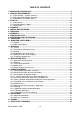
TABLE OF CONTENTS 1. DESIGN AND INTENDED USE .......................................................................................... 4 2. SECURITY REQUIREMENTS............................................................................................. 6 2.1. ATEX marking – symbols meaning .............................................................................. 7 2.2. Rating plates for indicator and scale ............................................................................ 8 2.3.
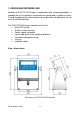
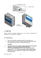
1. DESIGN AND INTENDED USE Indicator of PUE C/31H/EX type, in cooperation with a weighing platform, is intended for fast and precise measurements performed in explosive areas. Tarring throughout the whole measuring range allows to determine the net mass of measured loads.
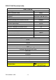
PUE C/31H/EX technical data: PUE C/31H/EX Housing type stainless steel Ingress Protection Rating IP66/67 Display type LCD Keyboard Microswitch (500 000 cycles) OIML class III Maximum quantity of A/D converter divisions 8388608 Number of verification intervals 6 000 Maximum input voltage 19,5 mV Maximum voltage per verification interval 3,25 µV 1 µV Minimum voltage per verification interval -10 oC ≤ ta ≤ 40oC Ambient temperature Minimum load cell impedance 125 Ω Maximum load cell impeda
2. SECURITY REQUIREMENTS Please read this manual carefully prior the first usage. Following the instruction, use the device as intended; PUE C/31H/EX indicator, and scales with design based on the indicator, can be used in explosive zone 1 and 2 where there is a mixtures of gases, vapours and mists of II (second) explosion group and T1, T2, T3 or T4 temperature class.
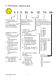
2.1. ATEX marking – symbols meaning Equipment group: I – underground parts of mines II – all other places liable to be endangered by explosive atmospheres Categories for group II equipment: 1 - the device assures a very high protection level, - to be operated in zones 0,1,2 2 - the device assures a high protection level, - to be operated in zones 1,2 3 - the device assures a standard protection level, - to be operated in zone 2 Explosive atmosphere: G – caused by gas, vapor and mist. D – caused by dust.
PUE C/31H/EX indicator is a device of group II with „ib” protection therefore “Gb” protection symbol may be omitted. 2.2.
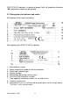
10 – WEEE symbol 11 – ATEX marking relating to the scale (see point 2.
Rating plate of the scale Protective sticker Verification sticker Functional grounding mark 3. START-UP Please read this manual carefully prior the start-up. Following the instruction, use the device as intended. 3.1. Scale placing • • • The scale should be unpacked outside the hazardous area. Before moving the scale to the place of operation prepare a cable for earthing the device against electrostatic charges.
NOTICE! Mounting the indicator, placing the weighing platform and earthing/zeroing should be performed when the explosive atmosphere cannot appear. Indicators with cable can be mounted on the rack, on the wall or on the table using a special mounting kit. Weighing platform should be placed on even and stable ground far from sources of hit and draughts. It should be also levelled out using the feet. 3.2. Connecting power supplier 1. Place the power supplier outside the hazardous area. 2.
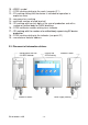
Safe area Hazardous area EX ZRi02 power supplier cable up to 20m AC 230v 50Hz Scale with the indicator on a pillar Safe area Hazardous area EX ZRi02 power supplier cable up to 20m AC 230v 50Hz Scale with the indicator on a cable Supplier connection EXI-01-04-06-14-GB - 12 -
1 – earthing terminal 2 – power supply socket description 3 – power supply socket 4 – power supply socket 5 – screened load cell cable Power connector parameters EXI-01-04-06-14-GB - 13 -
3.3. Switching on • Press the ON/OFF key – keep pressing for about 1 sec. • After switching on, wait for the test completion. • The indication shall equal zero and the following pictograms shall be seen: - zero indication - equilibrium kg - weighing mode • If the indication does not equal zero press the zeroing key . Ready to use. 4. CLEANING Cleaning can be performed only after unplugging from mains (230V AC).
In case of any problems with appropriate operation of the indicator, contact the manufacturer’s service centre or any service centre authorised by RADWAG. In case of any fault or dysfunction the device should be passed to the manufacturer’s service centre or, if this is not possible, the fault should be reported in order to settle the conditions of repair. Any intrusion (alteration, repair etc.
7. KEYBOARD Information window Display window Function keys – „keypad” 8. FUNCTINS OF KEYS Power on/off – keep it pressed for about 1 sec Function key (selection of operation mode) Confirmation of changes - zeroing - tarring NOTICE: and keys results in change of particular keys functions, Pressing wherein the change is valid until setting parameters procedure is completed. See the further part of the manual for details.
9. INSCRIPTIONS AND PICTOGRAMS O.n. Inscription Description 1. 2. 3. FIL PCS HiLo Filtering level Parts counting +/- control in relation to reference mass 4. Auto 5. toP Measurement of max. force influencing weighing pan 6. Add Totalizing Control and correction of zero indication of scale 7. Scale in autozero range (indication = precise zero) 8. Result of measurement is stable (ready for readout) 11. PCS kg (g) Net 12.
P3 Unit P3.1 P4 Func P4.1 P4.2 P4.3 P4.4 P4.5 P4.6 P4.7 P4.8 P4.9 P6 CAL P6.1 P6.2 StUn | kg FFun Funi PcS HiLo PrcA Prcb AtAr toP Add | | | | | | | | | ALL no no no no no no no no St_u uCAL | | * FUNCTION * * FUNCTION * 11. BROWSING USER’S MENU User moves in the menu using the scale keyboard. 11.1.
11.2. Return to weighing NOTICE: Changes introduced into the scale memory will be permanently saved after return to weighing. several times, keep pressing until message Press F key is seen. Return to weighing Upon noticing the message press: key – for changes confirmation or key – for resigning. After completion of this procedure the scale returns to weighing. 12. WEIGHING Place a load on a weighing pan. After noticing stability pictogram, , read the weighing result. 12.1.
function pay attention to maximum weighing range, it cannot be exceeded. After removing the load and the package, display shows indication of sum of tarred weights with minus sign. NOTICE: Tarring may not be performed when minus value or zero is displayed. In such a case the display shows message, short sound signal is heard. 12.2. Tarring by inscribing tare value It is possible to inscribe a tare value.
NOTICE: Tarring by inscribing tare value cannot be performed when the tare value has already been implemented into the scale memory. In such a case the display shows message, short sound signal is heard. 12.3. Zeroing In order to zero the indication press zeroing key and . on a display next to symbols: . Zero value is shown The new zero point is treated by the scale as the precise zero. Zeroing is possible while stable status is shown on the display.
12.5. Setting a basic weighing unit The user may set a weighing unit to be active after turning on the scales. Procedure: • Following point 11 of this manual enter submenu, next: • Press key several times to view available units: Selection: A. When the basic unit is set to [kg], users can toggle between: [kg, lb, N]. For verified scales [lb] is not accessible. B. When the basic unit is set to [g], users can toggle between: [g, ct]. For verified scales [lb] is not accessible.
Save changes and return to weighing: See point - 11.2. – return to weighing. NOTICE: Upon activation the scale operates with a set basic unit. 12.6. Temporary weighing unit This function allows users to choose unit for indication. The unit is valid until the scale is switched off or until another unit is chosen. In order to perform the following procedure, operation mode must be accessible, see point 14.1.1 – Enabling operating modes.
13. MAIN PARAMETERS User can adjust the scale to external ambient conditions (setting filters) or individual requirements (autozero, tare value). Respective parameters can be found in parameters group. 13.1. Adjustment of filtering level Procedure: • Following point 11 of this manual enter submenu, next: 1 - 4 - filtering levels to be selected (depending on the ambient conditions) Return to weighing: See point - 11.2. – return to weighing.
13.2. Autozero „AUTOZERO” function has been introduced in order to ensure precise indication. The intended use of this function is automatic control and correction of zero indication. When function is active comparison of results takes place at specified time intervals. If results differ by value smaller than declared AUTOZERO range, e.g. one division, scale is zeroed automatically, stable state is marked – and zero indication – is displayed.
13.3. Tare function operation This function enables the user to set appropriate parameters (depending on needs) for tare function. Procedure: • Following point 11 of this manual enter submenu, next: tArA AtAr - automatic tare function on - stored in scale memory after unplugging it from mains (see point 15.5 for description); tArA no - automatic tare function off (scale tarring by means of T key tArA tArF - ) tare memory function – stores last value of tare in scale memory.
13.4. Median filter The role of the median filter is to eliminate short lasting interference (e.g. mechanical shocks). Procedure: • Following point 11 of this manual enter submenu, next: Fnnd Fnnd no - median filter disabled YES - median filter enabled Return to weighing: See point - 11.2. – return to weighing.
13.5. Determining the minimal load S_Lo parameter works for automatic tare. The rule is that no automatic tare is performed until the indication drops below S_Lo value (gross). Procedure: • Following point 11 of this manual enter submenu, next: Select the digit to be set Select the digit value Return to weighing: See point - 11.2. – return to weighing. 14. OPERATION MODES 14.1.
no - mode disabled YES - mode enabled NOTICE: Enabling procedure for other operation modes is analogous to the one described above. Return to weighing: See point - 11.2. – return to weighing. 14.2. Determining number of accessible modes all the operation The user may decide whether upon pressing F key modes are to be accessible (option ), or only one, selected out of the list. Procedure: • Following point 11 of this manual enter
Return to weighing: See point - 11.2. – return to weighing. 14.3. Counting parts of identical weight The standard solution is equipped with option of counting small pieces of the same mass. If parts counting is to be performed in a container, its weight must be recorded into the scale memory (the container must be tarred). NOTICE: 1. Counting pieces mode does not operate with other functions, 2. Parts counting function is not active after scale’s restart.
• The blinking value on the display informs of quantity of a sample. By means of confirm: key, set quantity of a sample and press key to • If option has been chosen than the most recent weight value of a single piece is displayed for 3 sec., the program proceeds to Parts Counting mode automatically setting the previously displayed value.
• Using where: value, • Press and keys, enter the demanded quantity of sample, - selection of the digit to be set, - selection of the digit key for confirmation, • message is displayed, the following window is seen: Pilsujący symbol Blinking symbol • If pieces are to be weighed in a container, it is necessary to tare it, next declared number of pieces must be put onto the weighing pan, their mass confirmed after stabilization of the indication (symbol on a display): • The program automaticall
3. If a single element weight is not greater than a reading unit, then message is shown on the scale display (see point 19. Error Messages), short sound signal is heard, next the scale returns to weighing. Function deactivation: Press F key twice. 14.4. +/- control referring to the inscribed standard mass The program allows entering checkweighing threshold values (Min, Max. Procedure: • Enter function (first make the operation mode accessible see point 14.
• Press key to confirm, the program proceeds to window for setting the upper threshold (Max): Select the digit to be set Select the digit value key to confirm, the program automatically returns to • Press weighing with threshold values recorded into the memory.
14.5. Per cent deviation with reference to standard mass This program allows to measure deviation in per cent with reference to a standard mass. The standard mass can be estimated by weighing (PrcA function) or inscribed by a user (PrcB function). 14.5.1. Mass standard weight determined by the measuring process Procedure: • Enter function (first make the operation mode accessible see point 14.
Function deactivation: Press F key twice. 14.5.2. Standard mass inscribed to scale memory Procedure: • Enter function (first make the operation mode accessible see point 14.
Function deactivation: Press F key twice. 14.6. Automatic tare This function is useful for fast net mass determination of weighed load when the tare value for each next load to be weighed is different.
14.7. Measurement of the max force – peak hold Procedure: • Enter function (first make the operation mode accessible - see point 14.1): • Max pictogram visible in upper part of the display is a confirmation of toP function activation: • Apply a force to the weighing pan. The display of scale will latch the maximum value of the force. • Remove loads from the pan. • Before next measurement press . Function deactivation: Press F key twice. 14.8.
• Enter function (first make the operation mode accessible - see point 14.1) • „P” letter visible on the left of the display is a confirmation of function activation: 14.8.2. Totalizing procedure • Following point 14.8.1 enter function, • Place the first load on a weighing pan.
• Upon indication stabilization press key, sum of the first and second weighing is displayed („▲” pictogram in the upper right-hand corner of the display): • In order to finish the procedure of totalizing, press load on the pan or after taking it off): (either with a key is pressed again while load is being placed on a • If the weighing pan, the sum of previously performed measurements is deleted, message is displayed - unload the pan to return to ZERO . Letter „P” will appear.
NOTICE: In case of a display range overflow in totalizing, the program displays error <5-FULL>. The user must either take the load off the pan and press key in order to complete totalizing or replace the load with another one (of lower mass) not resulting in display range overflow. Function deactivation: Press F key twice. 15.
• The following messages are displayed: • A new start mass is adjusted during this period of time. After that a mass of calibration weight is shown (e.g. 3 000kg).
• Take off the load, message is displayed for 1 sec., the scale shows the adjustment submenu name: • Adjustment process may be interrupted at any time by pressing key, the following message informs about abortion of a process: NOTICE: 1. It must be remembered to perform calibration when the pan is unloaded! 2. If the adjustment takes more than 15 sec. the program displays an key and error message , short sound signal is heard.
• the program displays the following set of messages: • upon completion of the start mass estimation process the scale shows the parameter name: • start mass estimation process may be interrupted at any time by pressing process: key, the following message informs about abortion of a NOTICE: If the start mass estimation takes more than 15 sec. the program displays key and an error message , short sound signal is heard.
16. ERRORS Err2 - Value beyond the zero range Err3 - Value beyond the tare range Err4 - Calibration mass or start mass beyond the acceptable range (±1% for weight, ±10 for start mass). Err5 - Mass of a single piece lower than the scale division.
EXI-01-04-06-14-GB - 46 -
MANUFACTURER OF ELECTRONIC EQUIPMENT RADWAG WAGI ELEKTRONICZNE POLAND, 26 – 600 Radom, Bracka 28 Phone: +48 48 38 48 800, phone/fax: + 48 48 385 00 10 Sales dpt.: + 48 48 366 80 06 www.radwag.