
Owner's manual
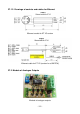
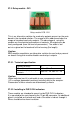
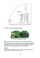

27.3. Relay module - PK1
Relay module PCB - PK1
This is an alternative solution for reed relay outputs present on the main
board in the standard solution. The usage of this module excludes the
usage of standard reed relay outputs. The advantage of using this
module are the electrical parameters of contacts. All outputs can be
freely configured (from the level of parameters). The cable is led
out via a gland on the back wall of the housing (3m length).
Caution:
PK1 modules constitutes an alternative solution for reed relays present
on board. Using this module disables reed relays‘ outputs.
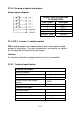
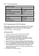
27.3.1. Technical specification
Quantity of relays 4
Wire diameter 0,14 ÷ 0,5mm
2
Current-carrying capacity of
contacts
230V AC - 2A, 30V DC - 2A
Caution:
When inductive load it is advisable to use a suppression circuit
(LC or voltage-dependent resistors) installed next to the receptor.
Parameters of these circuits are determined by clients.
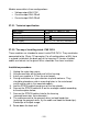
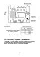
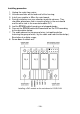
27.3.2. Installing in PUE C41H indicators
These module are intended to mount inside PUE C41H indicators.
It is mounted to the main board to the 10-pin J3 connector. An additional
gland is installed on the back wall and a 3m cable is led out through it
Wires should be free from insulation.
- 125 -