User Manual Scales of WPY/KO series Manual number: ITKU-47-06-03-10-A Mass Comparator MANUFACTURER OF ELECTRONIC WEIGHING INSTRUMENTS RADWAG Wagi Elektroniczne, 26–600 Radom Bracka 28 Street - POLAND Phone +48 48 38 48 800, phone/fax. +48 48 385 00 10 Selling department +48 48 366 80 06 www.radwag.
MARCH 2010 2
Table OF CONTENTS 1. INTENDED USE ..........................................................................................................................7 2. PRECAUTIONARY MEASURES ................................................................................................7 3. WARRANTY CONDITIONS ........................................................................................................7 4. UNPACKING AND MOUNTING............................................................................
15. COMMUNICATION..................................................................................................................34 15.1. RS 232 settings .................................................................................................................35 15.2. ETHERNET setting ...........................................................................................................35 15.3. TCP protocol setting ................................................................................
22.3. Checkweighing..................................................................................................................62 22.4. Tare mode.........................................................................................................................62 22.5. Labelling mode..................................................................................................................63 22.5.1. Setting of the number of labels to print ...................................................
28.4.4. Set tare value ..........................................................................................................92 28.4.5. Send the stable result in basic unit .........................................................................93 28.4.6. Send the result immediately in basic unit ...............................................................93 28.4.7. Send the stable result in current unit ......................................................................94 28.4.8.
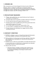
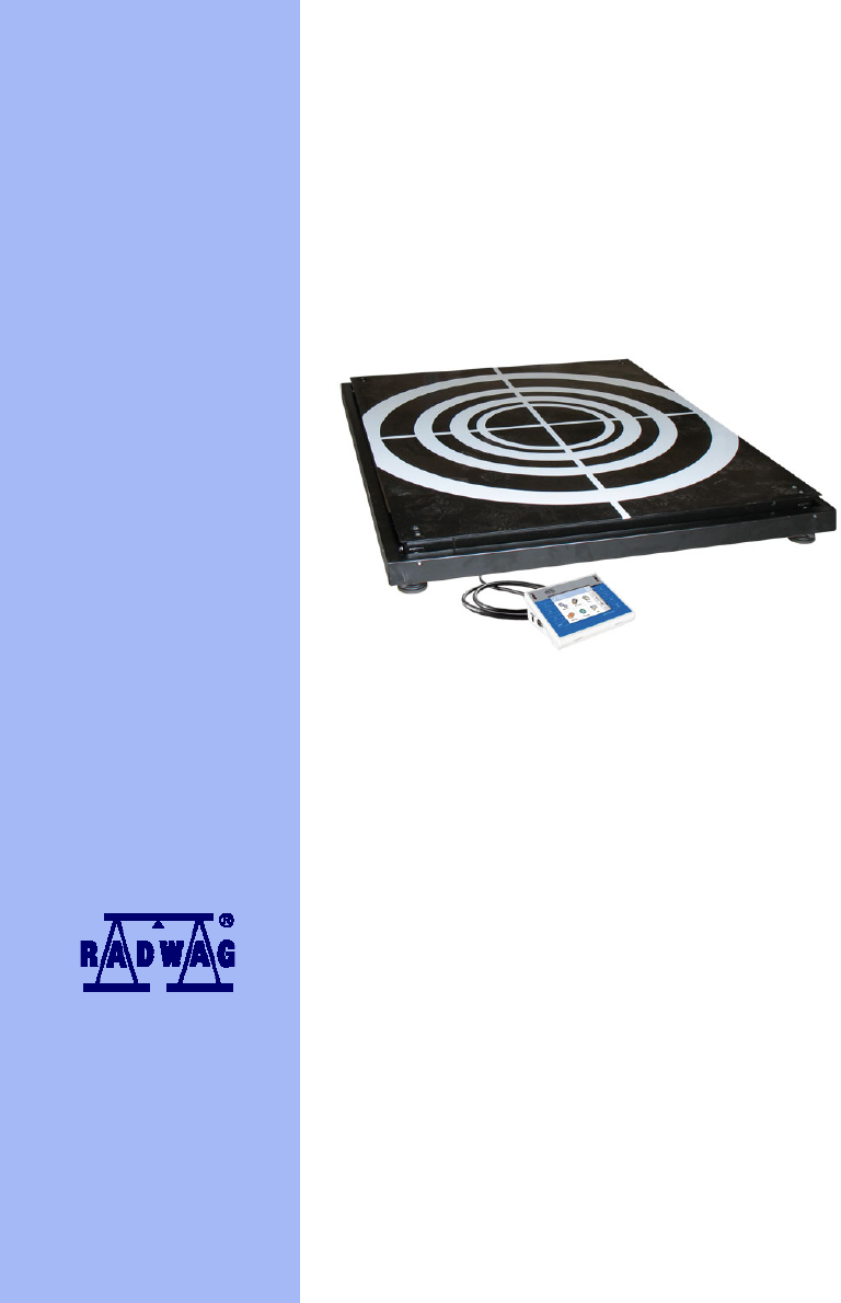
1. INTENDED USE Mass comparators are devices designed for determining the differences between masses of calibration weight (B) and reference weight (A). Comparators are most often used in measuring laboratories for calibration of weights and masses. Radwag offers comparators designed for calibration of weights and masses class M1 according to OIML R111. 2. PRECAUTIONARY MEASURES A. Please, read carefully this user manual before and use the device according to its intended use; B.
• Inappropriate cleaning. E. Forfeiture of warranty appears after: • Access by an unauthorized service, • Intrusion into mechanical or electronic construction of unauthorized people, • Installing another operating system, • Removing or destroying protection stickers. F. The detailed warranty conditions one can find in warranty certificate. G. Contact with the central authorized service: +48 48 384 88 00 ext. 106 or 107. 4.
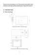
Every foot can be screwed in or out. This way only a smal range of level regulation is achievable. Basic levelling should be performed by putting steel pads under legs and observing the level on external level device. 5. CONSTRUCTION 5.1.
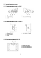
5.2. Description of connectors 5.2.1. Connectors’ description in PUE 7 1 – Ethernet RJ45 2 – RS232 (COM1) 3 – USB 1 – power supply socket 2 – I/O, RS232 (COM2) 5.2.2. Connectors’ description in PUE 7P 1 – Ethernet RJ45 2 – RS232 (COM1) 3 – USB 1 – I/O, RS232 (COM2) 5.2.3.
5.2.4. Connector with RS232 and I/O RS232 - DB9/M (male), top view: Pin2 - RxD Pin3 - TxD Pin5 - GND I/O, RS232 DSUB15/F (female), top view: Pin1 - GNDWE Pin2 - OUT1 Pin3 - OUT2 Pin4 - COMM Pin5 - 6÷9VDC Pin6 - IN4 Pin7 - IN3 Pin8 - TxD2 Pin9 - 5VDC Pin10 - GNDRS Pin11 - IN2 Pin12 - IN1 Pin13 - RxD2 Pin14 - OUT4 Pin15 - OUT3 6. GETTING STARTED • After the terminal is connected to power the ON/LOAD diode starts to light. to start the operating system loading procedure.
7. KEYPAD OVERLAY 8.
9. PROGRAM STRUCTURE The main menu has been divided into three functional groups. In every group there are parameters of similar use. 9.1. Main menu items The main menu comprises three functional groups: Parameters Databases Info 9.1.1.
9.1.2. Databases Icon Description Products Operators Weighings / Alibi Contractors Packages Warehouses Labels Delete older data Export database weighings to a file 9.1.3. Scale Info Submenu < Info> is for viewing information: • Scale factory number, • Program version, • Scale program version.
9.2. Inventory of parameters 9.2.1. Scale parameters - weighing Icon Description Value Platform 1 - Median Filter 0.5 Filter Fast Autozero Yes LO threshold 0 9.2.2. Working modes Icon Description Value Weighing - Save Mode Manual, each stable Down-weighing No Checkweighing No Tare mode No Labelling mode - Number of labels 1 No. of cumulative labels 1 No.
Threshold 100 CC label automatic triggering - Mode None Threshold 100 Statistics Global Counting pieces - Save Mode Manual, each stable Down-weighing No Checkweighing No Tare mode No Labelling mode - Number of labels 1 No. of cumulative labels 1 No.
Deviations - Save Mode Manual, each stable Down-weighing No Checkweighing No Tare mode No Labelling mode - Number of labels 1 No. of cumulative labels 1 No.
9.2.3. Communication Icon Description Value COM1 - Baud Rate 9600 Data bits 8 Stop bits 1 Parity None COM2 - Baud Rate 9600 Data bits 8 Stop bits 1 Parity None Ethernet - DHCP No IP Address 192.168.0.2 Subnet mask 255.255.255.0 Gateway 192.168.0.
9.2.4. Devices Icon Description Value Computer Port None Address 1 Printer - Port COM1 Code page 1250 Printouts - Weighing printout pattern See ch. 16.2.3 Product printout pattern See ch. 16.2.3 Cumulative printout pattern See ch. 16.2.3 Cumulative printout pattern for cumulative data See ch. 16.2.3 Operator printout pattern See ch. 16.2.3 Contractor printout pattern See ch. 16.2.3 Warehouse printout pattern See ch. 16.2.3 Package printout pattern See ch. 16.2.
Code length 0 Transponder card reader - Port None Additional display - Port None Pattern See ch. 16.2.3 *) Not related to „Comparator”. 9.2.5. Display Icon Description Value Text information - Displaying pattern See ch. 17.1.
Screen button 3 Statistics C: Print Screen button 4 CCStatistics : Print Screen button 5 C Statistics : Zero Screen button 6 Choose package Screen button 7 Edit batch number Screen button 8 None Screen button 9 None Left proximity sensor None Right proximity sensor None Set Default - Show all platforms No Bargraph type None 9.2.6.
Output 2 None Output 3 None Output 4 None 9.2.7. Authorizations Icon Description Value Anonymous operator Operator Date & Time Administrator Printouts Administrator Databases Products Administrator Contractors Administrator Packages Administrator Warehouses Administrator Labels Administrator Delete older data Advanced Operator 9.2.8.
Beep Buttons Touch screen calibration - 9.2.9. User Calibration An option only for non-verified scale Icon Description Value Platform 1 - Setting of start mass - Calibration - 10.
In the main application window one can see four separate parts: • In the top part of the window there is a status bar where a work mode, logged-in user and time&date are displayed. • Below the status bar you can see weighing window(s).: • There is a workspace below this window: Notice: The workspace is freely programmable. The default pattern is described in ch. 17.1.1 of this manual. • There are screen buttons below the workspace: Notice: 1. Users can define screen function buttons.
• In operating mode 9buttons are at ones disposal displayed subsequently from 1 to 9 starting from the left side, • In operating modes: or one can define up to 7 screen buttons displayed subsequently from 1 to 7 starting from the left side. Two buttons on the right side are attributed permanently to the modes mentioned above because of the functions that are ascribed to them. 11.
11.3. Authorization access levels Weighing software uses four access levels: administrator, advanced operator, operator, none. Every user with any attributed access level can perform weighings and select data from in databases to be used during weighing. Access to user parameters, databases and working modes depending on the authorization access level attributed: Operator type Access level description None No access to user parameters. Cannot start procedure „Comparison”.
It can be declared in submenu < Authorizations>, which is accessable only for users with the authorization level (see ch. 19 of this manual). 2. A user logged in as in submenu < Authorizations> (see ch. 19 of this manual) can change authorization levels for accessing different databases and functions < < Delete older data>. The exception are database Weighings / Alibi>, that have the status „Read only”. 12.
Searching a database according to a name Searching a database according to a code Printing on item from a database Clearing an editing field Screen keyboard on / off Reading a printout pattern from a *.lb file (active after connecting a pendrive) Variables for a printout pattern One level up 12.2. Return to weighing The changes introduced are saved for good after they are several times until the following confirmed. Press message box appears: Press: – to confirm changes or changes.
13. WEIGHING Put a load on the weight pan. When pictogram indication is ready to read. is displayed the Notice: A weighing can be saved after stabilising a measurement over zero ). (pictogram 13.1.
• Avoid side loads, particularly side strokes: 13.2. Zeroing In order to zero the indication choose a platform on the touch panel and . After zeroing is performed the indication is equal zero and press and . following symbols usually appear: Zeroing is possible only when the indication is stable. Notice: Zeroing is possible only within ±2% of full range around zero. If the zeroed value is beyond the interval of ±2%, Err2 is displayed. 13.3.
13.4. Inscribing tare It is possible to inscribe a tare value. Procedure: , • While in any work mode press then the screen keyboard is displayed, , • Inscribe tare and press • The program returns to weighing and the and the display shows the entered value with the „–” sign provided there was zero before on the display. 13.5. Weighing for dual range scales Switching between the I range and the II range happens automatically (exceeding Max of the I range).
Notice: The procedure of attributing functions to buttons and proximity sensors is described in ch. 17.2 of this manual. Possible selection: • While the main unit is [kg], users can choose between: [kg, lb, oz, ct, N, g] but for verified scales [lb, oz, N] are not accessible; • While the main unit is [g], users can choose between: [g, kg, lb, oz, ct, N] but for verified scales [lb, oz, N] are not accessible. 14.
14.1. Median filter The median filter is intended for eliminating short-lasting mechanical shocks. Procedure: • Enter < < Weighing> according to ch. 14 of the manual, select Median Filter> and then set an appropriate value. Accessible settings: None - median filter is off 0.5, 1, 1.5, 2, 2.5 - filtering level to choose 14.2. Filter This filter is intended to suppress continuous mechanical vibrations at the cost of stabilization time. Procedure: • Enter < < Weighing> according to ch.
If AUTOZERO is disabled zero is not corrected automatically. However, in particular cases, this function can disrupt the measurement process e.g. slow pouring of liquid or powder on the weighing pan. In this case, it is advisable to disable the autozero function. Procedure: • Enter < Weighing> according to ch. 14 of the manual, select Autozero> and then set an appropriate value. < Accessible settings: NO YES - Autozero off Autozero on 14.4.
The communication can be configured in parameters’ group Communication>. < In order to enter < „ Communication>, press Parameters / and then: Communication”. 15.1. RS 232 settings Procedure: • Enter < < Communication> according to ch.15 of the manual, select COM1> or < COM2>, and then set an appropriate value. For RS 232 following parameters are accessible: • • • • Baud Rate Data bits Stop Bit Parity - 4800, 9600, 19200, 38400, 57600, 115200 bit/s - 5, 6, 7, 8 - No, 1, 1.
15.3. TCP protocol setting TCP (Transmission Control Protocol) is a protocol for communication between two computers. It operates in mode client-server. Server awaits on connection iniciation on a specified port while client initiates connection to the server. Scale software allows setting the port for the „Tcp” protocol.
16.1.2. Computer address Procedure: • Enter < Devices> parameter group as described in chapter 16 of the manual, Computer / Address” then the window
• Choose „ with the screen keyboard appears, • Enter the required address and confirm it by pressing . 16.2. Printer In < Printer> submenu users can: • Setting communication with a printer, • Setting code page of a printer, • Setting patterns of printouts. To enter < „ and then: Printer>, press Parameters / Devices / Printer” 16.2.1.16.2.2. Printer code page Procedure: • Enter parameters < of the manual, Devices> as described in chapter 16 Printer / • Choose „ will be displayed, Code Page” then the screen keyboard • Write the required code page and confirm by pressing . Notice: The default value is 1250 – code page for Middle-East Europe. 16.2.3. Patterns for printouts Enter < Printouts> to define printout patterns.
Default printouts’ settings: Weighing Printout Pattern {1} Product Printout Pattern {50} {51} Cumulative Printout Pattern N={15} SUM={16} Cumulative of Cumulative Printout Pattern N2={20} SUM2={21} Operator Printout Pattern {75} {76} Contractor Printout Pattern {85} {86} Warehouse Printout Pattern {130} {131} Package Printout Pattern {80} {81} {82} CPG report printout pattern (Control of Packaed Goods) * Average tare report printout pattern (Control of Packaed Goods) * *) Not related to
• Communication port for a barcode scanner, • Offset setting (a number of characters that are omitted while reading), • Code length (number of characters that are analysed counting from the offset). Notice: Communication> set the baud rate (default 9600b/sec). In submenu < The detailed description of cooperation scale – barcode scanner can be found in APPENDIX F in this manual. 16.3.1. Port for barcode scanner Procedure: • Enter < „ Devices> according to ch.
16.3.3. Code length Number of characters that is considered while searching the assortment database. Procedure: • Enter < Devices> according to ch.16 of the manual, • Choose „ Barcode Scanner / keyboard is displayed, Code Length” then the screen • Write a new length and confirm it by pressing . 16.4. Transponder card reader Selecting operator (logging in) can be done in two ways: • Typing a password on a keyboard, • Approaching a transponder card to the reader. The card needs to be registerd first.
16.4.2. Procedure of attributing the card number to an operator To use a transponder card to log on an operator the card needs to be ascribed to the operator in the database of operators. Procedure: • Connect the transponder card reader to the required communication port (RS 232 COM1 or RS 232 COM2), • Choose a communication port for the reader (see ch. 16.4.
• RS 232 (COM1), • RS 232 (COM2), • Tcp. 16.5.2. Communication protocol frame PUE 7 weighing indicator with following displays: • WD display, • WWG display. To start cooperation of PUE 7 with displays go to parameter < and define an appropriate communication protocol. Sample> Procedure: • Enter parameters’ group < manual, Devices> according to ch.
17. DISPLAY Users can adapt the main display and visible information to their needs. All parameters of the display can be found in the parameters’ group Display>. < Entering < Display> can be made in two ways: • Direct pressing in the work area of the main display, and then: „ • Pressing Parameters / Inventory of parameters of the main display: Text information Buton functions Show all platforms Bargraph Type 17.1.
17.1.1. Display patterns The main application window comprises a work area including information that can be freely configured by a user. Procedure: • Enter < Display> according to ch. 17 of this manual, Text information / Displaying pattern”, then an • Choose: „ editing field with prompted value is displayed together with the screen keyboard, • Modify the pattern if necessary and confirm the changes by pressing . Notice: There are additional buttons in the bottom line of the screen keyboard.
17.1.2. Screen font The font type can be changed in the display workspace. Procedure: • Enter < Display> according to ch. 17 of this manual, • Choose: „ type. Text information / Font” and set the required font Accessible fonts: • Arial, • Courier. 17.1.3. Font size Setting the font size for the workspace in the display. Procedure: • Enter < Display> according to ch. 17 of this manual, • Choose: „ font size.
• Choose: „ Text information / Bold” and choose a setting. Accessible settings: NO YES - Bold is off Bold is on 17.2. Function keys In submenu < Actions> users can set actions following keys: function keys, screen keys, proximity sensors. If a button has been attributed a function it has been activated at the same time. If a button or sensor has no ascribed a function in stays inactive. Procedure: • Enter < Display> according to ch.
• By pressing a formerly defined button or proximity sensor < Change platform>. • By activating in parameters all platforms that will be separately placed in the main window of the program. In that case platforms can be activated by pressing the area of this platform. Notice: The procedure of attributing functions to buttons and proximity sensors is described in ch. 17.2 of this manual; To activate all platforms press „ Parameters / appropriately.
17.4.1. Bargraf “Quick weighing” • The bargraph consists of 8 red fields and three green fields. • The green fields signal weighings between MIN and MAX threshold, where: MIN = the minimum threshold of acceptable weighing - LO MAX = the maximum threshold of acceptable weighing - HI • If a measurement is over the MIN (to the value of 1/3 of MIN-MAX) the green field with a triangle on the left is visible. If the measurement is between 1/3 and 2/3 of MIN-MAX the rectangular green field is visible.
• The central green field – signals that the load on the pan is within the set required interval for the weighed product (OK value between Min and Max thresholds); • The right red field – signals that the load on the pan is greater than the maximum weighing threshold (Max threshold). 18. INPUTS / OUTPUTS WPY/KO scales are equipped with 4 inputs / 4 outputs. To adjust software to the users needs configure inputs outputs in the submenu Inputs / Outputs>: < • • indicator inputs, indicator outputs.
18.2. Configuration of outputs Ascribing a function to the output enables the output at the same time. If an output has no ascribed function it is disabled. Procedure: • Enter < Inputs / Outputs> according to ch.
19. AUTHORIZATION The submenu < Authorization> is accessible only while being logged in as the Administrator. In this group of parameters access levels can be outlined. To enter submenu < Authorization>, press „ Authorization”. Parameters / and then: 19.1. Anonymous Operator The program allows to attribute the authorization access level to an operator who does not perform the log-in procedure (anonymous operator). Procedure: • Enter < Authorization> according to ch.
Accessible authorization levels: None, Operator, Advanced Operator, Administrator. Notice: Setting allows free access to settings of date and time (without the need of logging in). 19.3. Printouts Default settings of the scale allows a logged on Administrator to edit printout patterns. Software allows to change the access level to option Printouts>. < Procedure: • Enter parameter group < Authorization> according to ch. 19 of this manual, choose < Printouts>, and set appropreately.
Procedure: • Enter parameters’ group < of the manual, choose < Authorization> according to ch. 19 Databases>, and then set the parameter. Accessible authorization levels: None, Operator, Advanced Operator, Administrator. Notice: Setting allows free access to settings of date and time (without the need of logging in). 19.5. Delete older data Default settings allow a logged-in Advanced Operator delete older data from the < Weighings / Alibi> database.
20.1. Languages Procedure: • Enter submenu < choose < Others> according to ch. 20 of this manual, Language> and set the parameter. Accessible languages: • • • • • • • • Polish, English, German, French, Russian, Spanish, Czech, Hungarian. 20.2. Setting date and time Users can set date and time that are visible in the main window of the display.
20.3. Sound signal Procedure: • Enter < Others> according to ch. 20 of this manual, < and set accordingly. Beep> Settings: None Buttons Sensors All - Sound for buttons and proximity sensors disabled Sound for buttons enabled Sound for proximity sensors enabled Sound for buttons and proximity sensors enabled 20.4. Touch panel calibration Touch panel calibration is required when inappropriate operation is recognized. E.g. the reaction in a different place than the touching point.
To enter < „ Customer Calibration>, press Parameters / and then: Customer Calibration”. 21.1. Calibration procedure • Enter submenu < and select: “ Customer Calibration> according to ch. 21 Platform 1 / Calibration”, • After entering the parameter the following message box appears: • Take the load off the pan of platform 1, • Press button .
• After the procedure of calibration factor determination following command appears: • Return to weighing, saving parameters. Setting of start mass> parameter allows to adjust < start mass of platform 1. Notice: The factory calibration process for platforms 2, 3, 4 is analogical to the one described above. Return to weighing: The changes introduced are saved for good after they are confirmed. Press several times until the following message box appears: – to confirm changes or Press: changes.
21.2. Start mass adjustment It is possible to adjust only a start mass, it helps to correct the start zero when the span does not change. Procedure: • Enter submenu < and select: “ Customer Calibration> according to ch. 21 Platform 1 / Setting of start mass”, • After entering the parameter the following message box appears: • Take the load off the pan of platform 1, • Press button .
22.
2. The change in on mode results in the same change for other working modes working modes. 22.1. Recording mode Depending on setting parameter < from the scale to an external device. Save Mode> users can send data Procedure: • Enter parameters group < to ch. 22 of this manual, • Enter the required mode and choose < the required mode. Working modes> according Save Mode> then choose Accessible options: • • • • Manual every stable, Manual first stable, Automatic first stable, Automatic last stable.
22.3. Checkweighing In case of enabling the checkweighing mode, printouts are performed only when a weighing is between MIN and MAX thresholds that have been defined before. Procedure: • Enter parameters group < of this manual, • Enter the required working mode and choose < then set the required option. Working Modes> according to ch. 22 Checkweighing> Options: No Yes - Every weighing is recorded Only weighings between MIN, MAX are recorded. 22.4.
Total sum - Summing up all subsequently entered tare values Autotare - Automatic tare mode together with mode 22.5. Labelling mode The labelling system is intended to print labels for marking weighed goods e.g. a packing process. The program can print standard labels for single products, cumulative labels for sticking to bulk containers and cumulative labels for cumulative labels for sticking to the large transport containers holding bulk containers.
• Enter the required working mode and choose: „ Labelling mode / Number of labels” then the editing field with the screen keyboard is opened, • Choose the required number of labels and confirm by pressing . 22.5.2. Setting of the number of cumulative labels to print No. of cumulative labels> define the amount In the parameter < of sum labels. They are printed on connected printer.
• Enter the required number od cumularive labels and confirm . by pressing 22.5.4. Automatic triggering of cumulative labels Users have access to the function of automatic triggering of printing cumulative labels after setting parameters < < Mode> and Threshold>.
By default setting button is accessible in the bottom part of the can be done in submenu: display but activating the button „ Parameters / Display / (see ch. 17.2 of the manual). Actions” For automatic printout of cumulative labels counters and total mass variables are always zeroed.
None - Cumulative label of cumulative labels printout is initiated by pressing Mass - or * , Cumulative label of cumulative labels printout is initiated by exceeding the value set in parameter < Threshold>. The value is treated as the total from single weighings, Number - Cumulative label of cumulative labels printout is initiated by exceeding the value set in parameter < Threshold>.
− If parameter < Mode> is set to use the screen keyboard to enter the required counter value as a threshold to trigger off printing CC labels. • Confirm the changes introduced by pressing . 22.6. Statistics All statistics are continuously updated after each measurement is saved in the scale memory. Statistics can be calculated globally (does not depend on the selected product) or separately for every product from the assortment database. It can be set in parameters < Statistics>.
To enable the function in parameters you need to: • Enter parameter group < Working modes> according to ch. 22 of this manual, choose: „ Counting Pieces / Automatic correction of reference mass” and set appropriate option.
22.8. Selecting the series type It concerns the < Comparator> working mode Procedure: • Enter group of parameters < Working modes> according to ch. 22 of this manual: „ Comparator / and then choose the right method. Method” Accessible methods: • ABBA • ABA 22.9. Declaration of the number of measurement series It concerns the < Comparator> working mode Procedure: • Enter group of parameters < to ch.
If a user has changed the operating mode to another follow the actions below: • While in the main window press the icon with mode name placed on the top bar on the left then submenu comprising all accessible working modes opens, • Choose < Weighing>, program automatically returns to the main window displaying icon in the top bar. 24.
24.2. Setting a reference unit by entering known piece mass Procedure: • Enter mode < of this manual, Counting Pieces> according to ch. 24.1 (enter piece mass), then an editing field is displayed • Press with the screen keyboard, • Enter a value and confirm it by pressing < , which causes starting Counting Pieces> with automatic setting the reference unit. Notice: 1.
• The program automatically calculates reference unit mass and causes starting < Counting Pieces>. Notice: • The total mass of all pieces put on the weight pan cannot be greater than the weighing range; • The total mass of all pieces put on the weight pan cannot be lesser than 10 d for verified scales and 100 for non-verified scales. If the conditions above are not fulfuled a message box is displayed: ; • The total mass of a single unit cannot be lesser than 0.
d) Choose option , then the standard unit mass is attributed to the product in the field . Notice: Attributing a standard to a selected product is also possible by programmable button. Setting programmable buttons is described in ch. 17.2 of this manual The list of functions is described in APPENDIX B of this manual. 25. WORKING MODES – DEVIATIONS The program allows to check weighings in deviations (in %) around an outlined standard mass.
• If the standard is to be weighed in a container, the container needs to be put on the pan and tarred, (Estimate standard mass), then a message is displayed: • Press , • Put the load on the pan. After stabilization the result is taken as a standard (symbol ). Confirm it by pressing , • At the same time the weight unit is changed to (w %). 25.3. Rederence unit mass inscribing into the memory Procedure: • Enter < Deviations> according to ch. 25.
The results are calculated according the tables below: For an ABBA series No A B B A D = Bav – Aav 1 2 3 4 5 ….. n D1 D2 D3 D4 D5 … Dn For an ABA series No A B A D = B – Aav 1 2 3 4 5 …..
• Standard deviation: 2 1 n ( s = Di − D X i ) ∑ n i =1 26.1. Starting the working mode Procedure: • While in the main window press in the top bar, then you will see a submenu comprising a list of modes, • Choose mode < Comparator>, program automatically returns to the main window displaying in the top bar the name of selected working mode, • Concurrently on the workspace of the window a message is displayed: . 26.2.
Caution: Users can terminate testing anytime by pressing the screen button (stop process) situated in the bottom part of the scale display. During testing the rest of screen buttons, function keys, and are not active.
a final report is printed out comprising • After pressing subsequent measurements and final calculations. An example report: 27.
Packages Warehouses Labels In order to enter < < Databases>, press and choose Databases>. 27.1. Searching databases Users can quickly search databases according to the following criteria: • Name, • Code. The quick search according to the criteria above is applicable for databases of: operators, products, contractors, packages, warehouses and labels. Additionally users can search the weighing database according to < weighing date>. 27.1.1.
27.1.2. Quick code search Procedure: • Enter < • Enter < Databases> according to ch. 27 of the manual, Products>, • Press , then an editing field appears with the screen keyboard, • Inscribe the name of a product or its part and press . • The program will automatically edit the required product. 27.1.3. Weighing date search Procedure: • Enter < Databases> according to ch.
Notice: Adding new records in databases is possible only by logged-in administrators. It does not concern the database of weighings. 27.3. Deleting items in databases Procedure: • Enter < • Enter < Databases> according to ch. 27 of the manual, Products>, • Give a long press to the item, then the context menu is displayed, • Press , then a message is displayed: , • Confirm it by pressing .
• Give a date before which data need to be removed and confirm it by pressing , Caution: If a user enters a date from the protected period the program displays a message box: . • After entering a date beside protected period the program displays a message box: , the program will start removing data • After it is confirmed by and after completing it displays the number of deleted records, • Press to leave. 27.5.
• Enter submenu < Databases> according to ch. 27 of this manual, • Enter option < Export database of weighings to a file>, the program automatically starts saving the database on the pendrive, Notice: In case a pendrive is not recognized after entering < Export database of weighings to a file> a message is displayed: . • After the operation has been completed: „Operation finished successfully” is displayed together with the file name (with extention *.
27.7.1. Operators’ database Procedure: • Enter < Databases> according to ch. 27 of this manual, • Enter < Operators> and press the required position. Record of operator: Name Operator name Code Operator code Password Password to log on (max. 16 characters) Access level Authorization access level Card number Transponder card reader for logging on 27.7.2. Database of products Procedure: • Enter < • Enter < Databases> according to ch. 27 of this manual, Products>and press the required position.
Max Maximum mass for checkweighing Tare Tare value (it is preset automatically after selecting a product) Price Unit price Number of validity dates Number of days to calculate expiery date Date Constant product date VAT Value Added Tax in [%] Ingredients Dialogue box for entering ingredients Label Basic label pattern attributed to a product C Label Cumulative label pattern attributed to a product CC Label Cumulative of cumulative label pattern attributed to a product 27.7.3.
Weighing record: Date Weighing date Mass Weighing result Tare Tare value Product Product name Operator Operator name Contractor Contractors name Batch number Number of produced batch Source warehouse Source warehouse name Target warehouse Target warehouse name Package Package name Checkweighing A weighing threshold (MIN, OK or MAX) 27.7.4. Database of contractors Procedure: • Enter < • Enter < Databases> according to ch. 27 of this manual, Contractors> and press the required position.
Contractor record: Name Contractor’s name Code Contractor’s code Tax ID Contractor’s tax ID Address Contractor’s address Postal code Contractor’s postal code City Town/City of contractor Discount Contractor’s discount Label Contractor’s label pattern 27.7.5. Database of packages Procedure: • Enter < Databases> according to ch. 27 of this manual, • Enter < Packages> and press the required position.
27.7.6. Database of warehouses Procedure: • Enter < Databases> according to ch. 27 of this manual, • Enter < Warehouses> and press the required position. Warehouse record: Name Warehouse name Code Warehouse code Description Additional warehouse description 27.7.7. Database of labels The database comprises patterns of labels which users can attribute to products or contractors to operate in labelling mode. Procedure: • Enter < • Enter < Databases> according to ch.
28. COMMUNICATION PROTOCOL 28.1. General information A. A character protocol scale-terminal has been designed for communication between RADWAG scales and external devices via RS-232 interface. B. It consists of commands sent from an external device to the scale and a responses from a scale. C. Responses are sent every time after receiving a command (reaction for any command). D. Using commands allows users to receive some information about the state of scale and/or influence the operation e.g.
Notice: 1. Each command have to be terminated in CR LF; 2. The best Policy for communication is not sending another command until the former answer has been received. 28.3.
28.4.2. Tarring Syntax: T CR LF Possible answers: T_A CR LF T_D CR LF - command accepted and in progress - command completed T_A CR LF T_v CR LF - command accepted and in progress - command comprehended but tare range overflow appeared T_A CR LF T_E CR LF - command accepted and in progress - time limit for stable result exceeded T_I CR LF - command comprehended but cannot be executed 28.4.3.
Notice: Use dots as decimal points in tare values. 28.4.5.
Frame format: 1 2 3 4 5 6 7-15 16 S I space stability space sign mass space 17 18 19 unit 20 21 CR LF Example: S I CR LF – computer command S I _ ? _ _ _ _ _ _ _ 1 8 . 5 _ k g _ CR LF - command done, mass value in basic unit is returned immediately. 28.4.7.
Possible answers: SUI_I CR LF - command comprehended but cannot be executed MASS FRAME - mass value in current unit is returned immediately Frame format: 1 2 3 4 5 6 7-15 16 S U I stability space sign mass space 17 18 19 unit 20 21 CR LF Example: S U I CR LF – computer command S U I ? _ - _ _ _ 5 8 . 2 3 7 _ k g _ CR LF - command executed and mass returned 28.4.9.
28.4.11. Switch on continuous transmission in current unit Syntax: CU1 CR LF Possible answers: CU1_I CR LF - command comprehended but cannot be executed CU1_A CR LF MASS FRAME - command comprehended and in progress - mass value in current unit is returned Frame format: 1 2 3 4 5 6 7-15 16 S U I stability space sign mass space 17 18 19 unit 28.4.12.
28.4.14. Set upper threshold Syntax: UH_XXXXX CR LF, where: XXXXX – mass format Possible answers: UH_OK CR LF - command executed ES CR LF - command not comprehended (wrong mass format) 28.4.15. Read lower threshold Syntax: ODH CR LF Possible answers: DH_MASA CR LF - command executed Frame format: 1 2 3 4-12 13 D H space mass space Mass Unit 14 15 16 unit 17 18 19 space CR LF 17 18 19 space CR LF - 9 characters justified to the right - 3 characters justified to the left 28.
28.4.17. Send all implemented commands Syntax: PC CR LF Possible answers: PC_A_”Z,T,S,SI,SU,SUI,C1,C0,CU1,CU0,DH,ODH,UH,OUH,OT,UT,PC" – command executed, the indicator have sent all the implemented commands. 28.5. Manual printouts / automatic printouts Users can general manual or automatic printouts from the scale. • Manual printouts can be performed after loading the pan . and stabilizing indication by pressing • Automatic printouts can be performed only after loading the pan and stabilizing indication.
29. CONNECTING EXTERNAL DEVICES WPY/KO scales can cooperate with the following devices: • • • • • • Computer, Receipt printer, Label printer, Additional display, Barcode scanner, Any peripheral device with the compatible ASCII protocol. 30. DIAGRAMS OF CONNECTION CABLES Notice: Cable „scale – Ethernet” is a standard network cable with RJ45 connectors on both sides.
Scale – printer (CITIZEN, EPSON) cable Scale – I/O cable 100
31. TECHNICAL PARAMETERS Scale type: Maximal range Readability Comparation range Repeatability Recommendations for rating weights OIML R111 Platform size WPY 500/KO WPY 1000/KO WPY 2000/KO 510kg 1100kg 2100kg 5g 10g 20g 0....510kg 0....1100kg 0....2100kg 5g 10g 20g 500kg - M1 1000kg - M1 2000kg - M1 1000 x 1000mm Stabilization time 5....
33. ADDITIONAL EQUIPMENT Accessories: • • • • • • • • • • • • KAFKA printer cable - P0136, Computer cable - P0108, EPSON printer cable - P0151, Thermal printer - KAFKA, Dot matrix printer - EPSON, Label printer - CITIZEN, Additional display in plastic casing - WD- 4/1, Large size display (2”) - WWG-2, Transponder card reader - CK-01, Barcode scanner - LS2208, Current loop in plastic casing - AP2-1, PC keyboard.
{3} {4} {6} {7} {8} {9} {10} {11} {12} {13} {14} {15} {16} {17} {18} {19} {20} {21} {22} {23} {24} {25} {26} {27} {28} {29} {30} {31} {32} {33} {34} {35} {36} Time Date & Time Net mass in current unit Net mass in calibration unit Gross mass Tare Current unit Calibration unit Minimum threshold Maximum threshold Batch number Cumulative Statistics: Number Cumulative Statistics: Sum Cumulative Statistics: Average Cumulative Statistics: Minimum Cumulative Statistics: Maximum Cumulative of Cumulative Statistics:
{54} {55} {56} {57} {58}** {59} {60} {61} {62} {63}** {64}*** {65} {75} {76} {77} {80} {81} {82} {85} {86} {87} {88} {89} {90} {91} {100}** {101}** {102}** {103}** {104}** {105}** {106}** {107}** {108}** {109}** {110}** {111}** Product: Tare Product: Unit price Product: Minimum Product: Maximum Product: Testing Prepackages mode (CPG) Product: Number of validity days Product: VAT Product: Date Product: Expiry Date Product: Density Product: Ingredients Product: Description Operator: Name Operator: Code Opera
{112}** {113}** {114}** {115}** {116}** {117}** {118}** {119}** {120}** {121}** {122}** {123}** {124}** {125}** {126}** {130} {131} {132} {135} {136} {137} {140} {141} {142} {143} {144} {145} CPG Report: Min CPG Report: Max CPG Report: Average CPG Report: Limit of the average CPG Report: Standard deviation CPG Report: Measurements CPG Report: Unit CPG Report: Report Number Average Tare Report: Date Average Tare Report: Result Average Tare Report: Standard deviation Average Tare Report: 0.
34.2. Formatting variables Users can format numeric, text and date variables intended for displaying or printing out. Different format commands: • • • • • • • Justification to the left, Justification to the right, Setting the number of characters for printout / display, Declaration of the number of digital places for numeric variables, Date&Time formatting, Formatting numeric variables for EAN13 codes, Formatting numeric variables and dates for EAN128/GS1-128 codes.
/ Date separator between days, months and years {2:yy/MM/dd} – Present date formatted as: year - month - day, where yy represents two less significant digits of year. \ „Escape” character removing formatting function form next character to allow it to be used as a character in a text string. {2:yy\/MM\/dd} – Present date formatted as yesr / month / day; {2:yy\:MM\:dd} –Present date formatted as: year : month : day.
35.
Start Stop Choose an operator Choose an operator by name Choose an operator by code Choose a product Choose a product by name Choose a product by code Choose a package Choose a package by name Choose a package by code Choose a contractor Choose a contractor by name Choose a contractor by code Choose a source warehouse Choose a source warehouse by name 109
Choose a source warehouse by code Choose a target warehouse Choose a target warehouse by name Choose a target warehouse by code Change working mode Counting pieces: Specify piece mass Counting pieces: Estimate piece mass Counting pieces: Ascribe standard Deviations: Specify sample mass Deviations: Estimate sample mass Emergency stop Chute permission Disable tare Change unit Change platform 110
36. APPENDIX C – Label pattern A label pattern can be created in 2 ways: • From the terminal level using variables, • Using PC software EDYTOR ETYKIET R01. A created project needs to be saved as an „lb” file then copied on a pendrive that can be connected to the terminal. Finally transfer the file to the database in the scale. While a label is in the database of labels it can be ascribed to products or/and contractors in order to work in labelling mode. 36.1.
36.2. Designing a label on a computer Example: Let us create a label pattern for the label below: Notice: The installer of EDYTOR ETYKIET R01 is accessible to download on website: www.radwag.com. on the overlap: Products / Measuring indicators / PUE7. Procedure: 1. Run software EDYTOR ETYKIET R01, 2. The following window appears: 3. Select the type of printer to cooperate with the scale and press the key .
Notice: Before starting the design process the label and printer parameters need to be set. The settings are described in the file: Help / Help / Program options / Settings. 4. To add a text in the label click on . Then following window appears: 5. In write the text: PORK CHARCUTERIE SMITH&SMITH Ltd, and confirm with the key . Then put it in the appropriate place of the label.
6. Click on the key confirm by pressing and in the field inscribe: {4} (date & time), and place it in the right place, 7. Place other texts and variables on the label in the same way as the one shown above. 8. Click on and expand list in opened window “Add graphics”: 9. Selected the required <*.bmp> file, confirm it with and put the draft in the proper place of the label. Notice: <*.bmp> on the label is printed after the draft is sent to printer memory.
11. In place write variable: {7:V6.3} (net mass for EAN13, 6-character code with three decimal characters), confirm it by pressing then place the code in the right place in the label. 12. Record the design of the label by selecting in software menu and then . Notice: Recorded patterns of labels in files with *.lb extension are not editable. This is advisable to record designs of labels in files with *.
36.4. Attributing a label to a product Procedure: • Enter < • Enter < Databases> according to ch. 27 of this manual, Products> and press the required item. Label>, then the database of labels is open with the list • Enter < of all labels, • Choose the required label. The program automatically ascribes the label to the product. 36.5. Attributing a label to a contractor Procedure: • Enter < Databases> according to ch.
2. Users can perform the test label printout – see ch. 27.5 of this manual. 37.
39. APPENDIX F - Communication with barcode scanners 1. For communication with barcode scanners RADWAG scales use RS232 interfaces and simplex transmission (one direction) without handshaking. Only two wires are required for assuring such a transmission. Used scanners should be equipped in such interface with disabled both hardware and software handshaking. 2. Both scales and scanners have the possibility of setting of transmission parameters.
MANUFACTURER OF ELECTRONIC WEIGHING INSTRUMENTS RADWAG WAGI ELEKTRONICZNE 26 – 600 Radom, Bracka 28 Street POLAND Phone +48 48 38 48 800, phone/fax. + 48 48 385 00 10 Selling Department + 48 48 366 80 06 www.radwag.