User manual no.: LMI-35-10/12/12/A Analytical balances XA/2X series BAL ANCES AND SCAL ES RADWAG 26 – 600 Radom, Bracka 28, POLAND Phone: +48 (0-48) 38 48 800, fax. +48 (0-48) 385 00 10 export@radwag.com www.radwag.
DICEMBER 2012 -2-
Table of Contents 1. TECHNICAL DATA .....................................................................................................................................5 2. UNPACKING AND INSTALLATION ........................................................................................................7 2.1. Balance XA/2X series ......................................................................................7 3. START UP ...............................................................................
14. SETTING ACCESSIBILITY OF MEASURING UNITS ......................................................................... 48 15. SETTING ACCESSIBILITY OF WORKING MODES ........................................................................... 49 16. OTHER PARAMETERS ........................................................................................................................... 49 17. WORKING MODES.......................................................................................................
1.
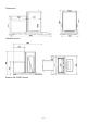
Dimensions: Standard version: Balance XA 52/2X/F series -6-
2. UNPACKING AND INSTALLATION 2.1. Balance XA/2X series Cut protective tape. Carefully remove the balance from its packaging. Remove from the box all necessary accessories needed for correct operation of the balance. Gently place the balance in its intended place of use. Install the weighing pan, and other elements according to below scheme. The balance is powered from mains through a power adapter: 110-230 V AC / 13,5-16V DC.
Analytical balance with weighing pan Φ 85 mm: - open side sliding glass doors of the weighing chamber, - place the bottom shield (4) inside the weighing chamber, - next, onto the bottom shield place a centering ring [pressed side facing downwards] (3), - inside the centering ring assembly the weighing pan (2), - place the anti-draft shield (1) onto the centering ring, - close side sliding glass doors of the weighing chamber, - plug the power adapter to mains, and plug the adapter’s pin to balance’s socket l
Analytical balance with an adapter for pipettes calibration: - open side and top sliding glass doors of the weighing chamber - place the bottom shield (8) inside the weighing chamber, - assembly the glass ring (7) onto the bottom shield, - place the weighing pan (6) inside the glass ring, - assembly the top ring (5) onto the glass ring, - assembly the evaporation trap (4) onto the top ring, - inside the glass ring place the vessel for pipette calibration (a beaker) (3), - assembly the top gla
Fig. 1.The components for assembling a balance XA/2X series On placing the balance in its intended place of use, assembly all of the components which come standard with the balance: • a bottom metal shield (4) of the weighing chamber • bottom ring (3) • a regular weighing pan (1) • weighing pan shield (2) On assembling the components and connecting the peripheral equipment, plug the balance to mains using the power adapter delivered to you with the balance.
3. START UP 3.1. Intended use • Place the balance on a firm and stable foundation / workbench free from air movement and vibrations. • The balance cannot be exposed to drafts and sudden gusts of air. • The balance should be placed in a weighing room with stabilized temperature and humidity. • The balance should be installed in a place distant from heat sources. • Ambient temperature in a weighing room should not exceed range between +10°C ÷ +40°C.
In case of analytical balance XA/2X series self-heating period takes approximately 1 hour. The specified time interval refers to balances that have been stored in room temperature before plugging to mains. For balances that were stored in much lower temperatures before plugging to mains (e.g. during winter period) thermal stabilization should last approximately 8 hours. During temperature stabilization time the indications on balance’s display may change. 4.
5. DESCRIPTION 5.1. Graphic display Fig. 3. Balance display 1. 2. 3. 4. 5. 6. 7. 8. Mass indication of weighed load or counted parts, Measuring unit, Pictogram denoting whether measurement result is stable, „BARGRAPH” presenting which part of accessible measuring range is in use, Text informing on enabled working mode, Current date, Current time, Pictogram denoting, that the indication is in precise. 5.2. Keyboard Each button of the balance’s keyboard operates as a dual-function key, i.e.
ON/OFF key enables switching on and off balance’s display. If switched off balance components other than the display are powered, and balance is in stand-by mode. F key. Function key, which enables quick entering the settings of an active working mode MODE key for selecting balance’s working mode. UNITS key, changes measuring units. PRINT/ENTER key - Sends current display status to a peripheral device (PRINT) or accepts selected value of a parameter or function (ENTER).
5.3. Sockets and interfaces 1. 2. 3. 4. 5. Power supply socket USB port(only in non legalization balances) Keyboard PS type socket Additional display socket RS232 socket Fig. 4. Interfaces of balance XA/2X series 6. USER MENU User menu of a balance XA/2X series consists of 9 main menu groups named using letter P and a corresponding number. The name and content of the menu is presented below. P1 Adjustment 01 Internal adjust. 02 External adjust.
P2 GLP 01 User 02 Project 03 Print time 04 Print date 05 Print user 06 Print project 07 Print Id 08 Print adjustment 09 Print adjust diff. | Smith John | | AR – 65/04 | | * * * * *0.0 | | * * * * *0.0 | | * * * * *0.0 | | * * ** * *0.0 | | * * ** * *0.0 | | * * * * *0.0 | | * * * * * *.1 | no no no no no no yes P3 Date/Time 01 Date format 02 Time format 03 Time 04 Date 05 Display time 06 Display date | * * * * * *0.0 | D/M/R | * * * * * *0.
P6 Printout 01 Printout no. 02 Printout 1 start 03 Printout 1 stop 04 Printout 2 start 05 Printout 2 stop ... . . . . . . . . . . 10 Printout editing 11 String 1 11 String 2 ... . . . . . . . . . . 89 String 80 | * * * * * *0.0 | standard | * * * * * *0.1 | | * * * * * *0.1 | | * * * * * *0.1 | | * * * * * *0.1 | | * * * * * *0. | | * * * * * * * * | function | * * * * * *0. | | * * * * * *0. | | * * * * * *0. | | * * * * * *0.
P9 Other 01 ID setting 02 Autom. ID print 03 Beep 04 Language 05 Backlight 06 Brightness 07 Contrast 08 Screen saver 09 Temperature 10 Factory no. 11 Software no. 12 Parameter printout 13 Upload parameters 14 Password protect. | * * * * * * * * | function | * * * * * *0.0 | no | * * * * * *0.1 | yes | * * * * * *0.1 | Polish | * * * * * *0.1 | yes | * * * * * * * * | function | * * * * * * * * | function | * * * * * *0.0 | no | * * * * * * * * | function | 114493 *0 .
Preview of balance menu – graphic presentation While in the weighing mode press SETUP key. The display opens balance’s main menu (display I). Press UP or DOWN navigating arrows on the balance’s overlay to move the cursor upwards or downwards in the menu content. Place the cursor next to a menu option to be previewed. Press RIGHT ARROW navigating key on balance’s overlay to open the submenu content (display II). Fig. 5. Preview of balance menu 1 – balance menu no.
6.1. Moving through the menu Moving in the user menu can be carried out using: Balance keyboard, External PC keyboard PS/2 type connected to balance’s socket, Commands sent from a connected computer to a balance 6.1.1. Moving in the user menu using balance keyboard Setup key. Entering balance’s main menu Moving the cursor down in the menu list Moving the cursor up in the menu list Selecting submenu for activating. On pressing the key, the display indicates the content of a selected group.
6.1.3. Moving in the user menu using external computer keyboard PS type Al keys and buttons located on balance’s overlay have their equivalents on a computer keyboard PS/2 type. See below table for reference: - equivalents of function keys Description ON/OFF key enables switching on and off balance’s display Function key for entering the main menu of a balance Selecting balance’s working mode, e.g.
- equivalents of ENTER / PRINT key and ESC key Accepting entered value of a parameter Abandon parameter changes and exit to to main menu 6.1.4. Moving in the user menu using virtual keyboard, via RS 232 interface Most of the functions controlled or set using balance’s overlay or an external computer keyboard PS/2 type can be carried out by a set of commands sent from a computer to a balance. The commands enable moving through user menu, setting parameters or controlling balance operation.
Fig. 8. Balance submenu – selection buttons 7. WEIGHING Basic working conditions for obtaining reliable measurement results: - Stable and constant temperature in a weighing room, - Stable foundation of a balance, - Selecting adequate balance settings adjusted to ambient conditions at a workstation. Before start of weighing process or in case of essential change of ambient conditions at a workstation (e.g. ambient temperature change at a workstation more than 1°C/h) the balance requires adjusting.
Press Units key to set a measuring unit. Place weighed object on balance’s weighing pan and read the result only on stabilization of the measurement. If the measuring unit is not displayed on pressing the Units key, then go to the corresponding submenu and check the accessibility attribute of the measuring unit. Mass indication of a load placed on balance’s weighing pan can be zeroed for multiple times. Pay attention not to exceed maximal capacity of a balance by applying multiple zeroing function.
Independently on pipette calibration option, the process requires assembling a dedicated adapter for pipette calibration featuring an evaporation trap (see user manual section: UNPACKING AND INSTALLATION”). The purpose of the evaporation trap is to minimize measurement errors occurring on liquid evaporation while its weighing. Before carrying out the pipette calibration process, pour distilled water to the 2/3 of the evaporation trap height.
7.2. User log in The users of a balance XA/2X series can have their specific access code to the balance’s menu. The password system is determined by balance’s administrator, i.e. a user of the higher order in relation to the other balance users. The access password can comprise up to 6 digits. Balance software enables determining: • • A single Administrator, who has access to all balance settings and software functions, including changing the password of the administrator and other users.
Fig. 9-1. Password protection – menu content - Administrator the field for inserting administrator’s password. Balance administrator has access to all balance functions and settings. - User the field for inserting user’s password. Balance user has access to the functions and settings which attribute is set to NO (i.e. no password protection). - Startup if the option is set to YES, then on balance startup the software requires entering a password (of the administrator or user).
Inserting Administrator’s password Enter a password for the balance administrator (a sequence of 6 digits) and for the user. Balance administrator has full access to balance menu. The user access is limited to the one described in previous point (balance menu, startup, adjustment, etc. options can be attributed YES/NO).
8. ADJUSTMENT In order to ensure the highest measuring accuracy, it is recommended to periodically introduce to balance memory a corrective factor of indications in relation to a mass standard – i.e. balance adjustment.
The time delay enables the user to take the weighed load of the weighing pan, if a weighing process is in progress. Pressing T/O key causes temporary delay of the adjustment process initiation. Automatic adjustment settings Fig. 12.
04 Adjustment test mass comparison of internal adjustment weight with its value saved in balance memory. 05 Internal weight correction The function enables correcting the value of internal adjustment weight. The function is disabled in verified balances.
Return to weighing mode Changes introduced in balance memory will be saved on returning to weighing with procedure of saving changes. Press ESC key for a few times until the display shows a question: Save? As displayed, select one of available options: ENTER – save changes and go back to menu; ESC – abandon changes and go back to menu. (see Fig. 9. Return to weighing mode. point. 6.1.2. Return to weighing mode). 8.3. Manual adjustment 8.3.1. Internal adjustment 1. 2. 3. 4. 5.
6. 7. 8. Load a weight / mass standard which mass is given on the display and press ENTER key. On completing adjustment process the balance returns to displaying submenu P1 - Adjustment Return to weighing mode – in accordance with point 6.1.2. If the DRH function is enabled in balance settings, then external adjustment process is disabled. The DRH function is enabled in verified balances (which are subject to conformity assessment). 8.3.3.
8.4. Adjustment report printout On completion of any type of adjustment process, the balance enables preparing a report from adjustment process. The report can be printed on a connected printer and sent to a computer and saved in a form of file for records. P1 08 Report printout : P1 08 Report printout : 1: yes 0: no – report printout enabled – report printout disabled Remember, that if the parameter is set for YES, then a report is generated and sent automatically. Fig. 15.
Fig 17. An example of a report from adjustment process 9. DETERMINING CONTENT OF A PRINTOUT FOR GLP PROCEDURES Menu P2 GLP is group of the parameters which enables declaring variables that are present on a printout from adjustment process. Fields referring to: - user (max 8 alphanumeric characters) - project (max 8 alphanumeric characters) are editable are enable entering a text using balance’s keyboard or connectable external computer keyboard PS/2 type.
01 Date format Enables two types of setting date format: - 1 date format Month/Day/Year - 0 date format Day/Month/Year On selecting appropriate date format accept it by pressing ENTER key. 02 Time format Enables two types of setting time format: - 1 time format 12 hours - 0 time format 24 hours On selecting appropriate time format accept it by pressing ENTER key. 12 hour time format is differentiated by letters PM or AM present on printouts.
Fig. 20. Submenu Date / Time – setting time – controlling keys Accept set value (the last digit stops flickering). Repeat the activity for other time values. On setting the new time value press ENTER key. The balance returns to displaying submenu P3 Date/Time. The time value visible in the upper bar graph of the display is changed. On setting required time value return to weighing mode as specified in point 6.1.2 of this user manual. 04 Date Press RIGHT ARROW KEY to enter parameter 04 Data.
05 Display time Available settings 1 – YES time displaying enabled, the upper bargraph of the display contains time, 0 – NO time displaying disabled. 06 Display date Available settings 1 – YES date displaying enabled, the upper bargraph of the display contains date, 0 – NO date displaying disabled. Return to weighing mode (see point 6.1.2. – Return to weighing mode) 11.
to 4 or 5). The effectiveness of filter operation differs in relation to the measuring range. The filter operates with lower accuracy while the mass indication is quickly increasing after placing a load on the weighing pan. Filter accuracy is increased when weighed mass is within filter’s set operation range (parameter: filter operation range is available only in balance’s service menu, and it is inaccessible for the user). 11.2.
11.6. Negative The function aids previewing mass value and other indications on the display. Depending on user needs it is possible to enable or disable the function. 11.7. Air buoyancy correction The air buoyancy correction enables correcting errors occurring while mass measuring processes, i.e.: 1. Determining mass of a sample which density considerably differs from the density of a mass standard used for adjusting the balance.
11.7.1. Means of operation The software enables two means of using the air buoyancy correction. 1. By inserting to balance memory known value of air density and known density value of weighed sample. After inserting these values the application automatically calculates correction factor for measured mass and after re-calculation of sample mass displays correct mass value. In order to avoid any errors, the re-calculated mass is proceeded by and exclamation mark (!) on the display and on a printout. 2.
Set value of parameter P4 07 Air buoyancy correction to 1: yes After returning to weighing mode with procedure of saving changes the display indicates pictogram (!). From now on the displayed mass is corrected in relation to buoyed air and density of weighed sample. Fig. 28-3. Balance menu – enabling air buoyancy correction In order to correct the mass of weighed object using air buoyancy correction mode, remember to apply current density values of the air and the weighed sample. 11.7.3.
Determining air buoyancy correction is also carried out using a dedicated set of 2 pieces of mass standards. One of the mass standards is made of stainless steel, and the other of aluminum. Each of the mass standards has specifically determined mass and density. Determining procedure: 1. Enter the density mode. 2. After entering the mode select appropriate procedure 3. On entering mode settings, set required data (mass and density) in the corresponding fields Fig. 28-6.
Fig. 28-8. Air density – declaring values of mass and density 4. 5. After inserting all required data start the determining procedure – move the marker to the START field and press F key Load the weighing with the stainless steel mass standard and on stabilization of measurement result press ENTER key Fig. 28-9. Air buoyancy correction – determining mass of a stainless steel mass standard 6. Mass of the stainless steel standard is saved in balance’s memory.
Fig. 28-11. Air buoyancy correction – the air density correcting coefficient At this stage the user can: − Restart the procedure from the beginning (by pressing Units key) − Return to weighing without saving changes on air density determination (press MODE key and select mode WEIGHING) − Accept calculated density value. Fig. 28-12. Air buoyancy correction – Message window 8. The display indicates the calculated values – the balance is ready for operation with the determined air density coefficient.
11.8. Operating conditions This parameter enables two settings: stable or unstable. Setting the parameter to stable causes much faster operation of the balance, i.e. the weighing time is shorter than compared to setting: unstable. This parameter refers to operating and ambient conditions at a workstation. If the conditions are unstable, then it is recommended to set the parameter to unstable. The default setting of the parameter is: stable.
12. RS 232 FUNCTIONS Balance XA/2X series enables defining parameters of balance communication with a computer or a printer. Fig. 23.
13. PRINTOUTS Printouts menu is dedicated for creating non-standard printout templates and selecting type of a printout which is printed. Detailed description of non-standard printouts is provided in point 18. of this user manual. 14. SETTING ACCESSIBILITY OF MEASURING UNITS This group of parameters enables setting accessibility of measuring units, which are available for an operator after pressing the Units key on balance’s overlay.
15. SETTING ACCESSIBILITY OF WORKING MODES This group of parameters enables setting accessibility of working modes, which are available for an operator after pressing the Mode key on balance’s overlay. Fig. 25. Working modes – settings All working modes which attribute is set to 1: yes are accessible from the main menu level under a key for toggling between the working modes. Changes to the parameter values are carried out in accordance with point 5.1.1 of this user manual. 16.
Selecting language version of software menu, available settings Polish or English 05 Backlight Determines whether the backlight of the balance’s graphic display should be enabled or disabled (enabling the backlight option improves data visibility on the display) 06 Screen brightness Enables changing the brightness of the balance’s graphic display – entering the function opens a window for setting brightness level using buttons on the balance’s overlay 07 Screen contrast Enables changing the contrast of
13 Acquire (upload) parameters Enabling this function causes uploading all parameters sent via RS 232 interface from a connected computer. On completing uploading process the balance informs a user on number of accepted and changed parameters, and number of incorrectly declared parameters which are rejected by the balance. Printing and uploading balance parameters is a very simple and intuitive means of setting new values of balance parameters.
17. WORKING MODES 17.1. Parts counting of the same mass The parts counting mode can be carried out suing three means: - inserting mass of a single part - determining mass of a single part from a standard quantity - selecting a part for counting from balance’s database 17.1.1. Counting by inserting mass of a single part Activate parts counting mode. Fig. 27. Parts counting – main menu Set reference mass and press ENTER key or move the cursor next to the field 07 Start and press RIGHT ARROW KEY.
Return to weighing mode - Press MODE key, the display indicates list of available working modes - move the cursor next to a field: MO Weighing - Press RIGHT ARROW KEY, the software returns to weighing mode and displays current measurement result 17.1.2. Counting by determining mass of a single part from a standard quantity Enable parts counting mode as described in point 16.1.1. independently on mass that has to be specified in field 01. Move the cursor next to a field 07 Start and press RIGHT ARROW KEY.
23- mass of all counted parts the pictogram of enabled Automatic Accuracy Correction function The display indicates mass of counted parts, that are loaded on balance’s weighing pan (i.e. 10 parts). If the added amount of parts is below the currently counted one, then the software automatically corrects mass of a single part. In this case it is APW = 5.2282 corrected to 5.1837. from now on the following parts are counted according to the new mass of a single part.
17.1.3. Selecting a part for counting from balance’s database Enable parts counting mode in accordance with below figure. Fig. 32. Selecting a part for counting from the database Select a record from the database, and start part counting process.
17.2. Checkweighing Checkweighing is a process intended for precise determining mass of a weighed sample with set and enabled checkweighing thresholds (limits). The thresholds are to visualize (by means of a bargraph located on the left side of the display) and monitor checkweighing process. Mode activating Fig. 33. Checkweighing – mode activating Display content Fig. 34.
4 – difference between mass of weighed sample and the center of the tolerance field (HI/LO) 5 – the values of low (LO) and high (HI) checkweighing thresholds 6 – a pictogram indicating the weighing range of currently weighed sample (available indications: LO, OK and HI) Remember to set the 02 Hi Threshold first, as the software automatically checks whether inserted values are correct and hold within the measuring range of a balance.
Fig. 36. Checkweighing – programming database of thresholds − Move the cursor to a field “Database of thresholds (limits)” and press RIGHT ARROW KEY Fig. 37. Checkweighing – programming database of thresholds – inserting thresholds values − − − − Enter a name for a selected record (name of a product to be weighed) Enter the value of HI threshold (limit) Enter the value of LO threshold (limit) Accept entered values by double pressing of ENTER key. Fig. 38.
− Move the cursor to a field “START” and press RIGHT ARROW KEY − The balance is ready to weigh a product with set checkweighing thresholds (limits). Fig. 39. Checkweighing – display content 1 – measurement result 2 – pictogram of stable measurement result 3 – working mode name 4 – the value of HI threshold (limit) 5 – the value of LO threshold (limit) 6 – a pictogram indicating the weighing range of currently weighed sample (LO – OK.
17.3. Filling Filling (dosing) mode is intended for precise measuring or adding a product until reaching a pre-defined target value. Before the beginning of a measuring cycle the user should set a target mass, which is simultaneous the HI dosing threshold. Mode activating Fig. 40. Filling – mode activating Display content Fig. 41.
17.4. Percent setup The purpose of this working mode is comparing mass of a weighed load with reference mass which is specified in mode settings. The result of the comparison process is displayed in percent. Working mode Percent Setup can cooperate with additional working modes: checkweighing, dosing and statistics. Mode activating Fig. 42. Percent setup – mode activating Display content Fig. 43. Percent setup – display content 1 – percent value, i.e.
Percent setup in cooperation with other working modes While activating the working mode go to its settings and set parameters: M4 03, 04, 05 to YES. Then move the cursor next to START field and start working mode operation. Caution: On enabling the Checkweighing mode in working mode settings remember to set the HI and LO checkweighing thresholds (limits) as values expressed in %. On enabling the Dosing mode in working mode settings remember to set the target value expressed in %.
8 – dosing mode enabled (load mass between 90 – 110%) On completing a measurement series, e.g. 10 measurements (no, of measurement N=10) the user can preview the result of carried out statistics from the measurement series.
17.5. Animal weighing Mode activating Fig. 46. Animal weighing – display content Internal mode settings FILTER (determines the speed (weighing time) required for stabilization of the final measurement result, the faster the filter setting, the shorter the measurement time.
17.6. Density determination of solids and liquids Additional equipment of a balance XA/2X series includes a kit dedicated for determining density of solids and liquids. Fig. 47 Components of a density kit Components of a density kit: 1. Beaker basis. 8. Hook. 2. Stand for weighing pans. 9. Top weighing pan for determining density of solids. 3. Sinker. 10. Pans flexible connection. 4. Beaker. 11. Bottom weighing pan for determining density of solids. 5. Thermometer handle. 12.
17.6.1. Density determining of liquids The basic component needed for determining density of liquids is a glass sinker with precisely determined volume, which value is indicated on sinker’s hook. Before carrying out density determining process enter the sinker’s volume value to balance’s memory. The density determining process is based on comparing mass of the sinker, first by weighing it in the air, and second by immersing it in the tested liquid.
17.7. Formulation Formulation mode is intended for preparing mixtures in accordance with pre-defined formulas. It is highly recommended for pharmacies. The software of balance XA/2X series features calculation memory, therefore it stores mass of each ingredient of a mixture and sums of weighed ingredients. While using formulation mode the balance’s display shows and continuously updates the following data: 1. Mass of a load placed on balance’s weighing pan 2.
parameter 03 No. of ingredients here the user can set number of ingredients in a prepared mixture (maximum no. of ingredients: 20) parameter 04 Formulation entering this parameter settings opens another submenu for specifying names (max 10 characters) and settings (target mass) for each ingredient in a prepared mixture. parameter 05 Formulation printout enabling this function causes printing parameters of an active formulation on a connected printer.
5 – Sum of all weighed ingredients of a formulation which are saved in balance’s calculating memory 6 – Number of already weighed ingredients in a prepared formulation 7 – name of currently weighed ingredient 8 – bargraphs on the left side of the display, which denote the mass to be added (dosed) to reach pre-defined mass of each weighed ingredient. While reaching the target mass the descriptions on accuracy visible on the bargraph are changing. Fig. 50.
− − − − − − − • • • • • • • • Total mass of a prepared formulation and mass of the vessel in which the formulation is prepared must not exceed maximum measuring range (max. capacity) of a balance A formulation can contain maximum 20 ingredients Parameter 03 No.
Means of preparing mixtures without entering data to balance memory on formation ingredients and their mass If a user needs a documentation from a formula making process, e.g. in a form of a printout, then set parameter 02 Automatic printout to 1 : YES. In such case each accepted mass of an ingredient (by pressing UNITS key) is automatically printed on a connected printer or computer. • • • • • • • • • Set parameter 01 Prompts (Hints) to 0 : NO.
17.8. Statistics Mode activation Fig. 52. Statistics – mode activation The very first process after entering the Statistics mode should be erasing the results of previous statistical calculations. It is carried out by using option M8 01 Erase. All statistical data are updated on an ongoing basis after saving a measurement result in balance memory.
Fig. 53. Statistics – display content including a series of measurements 1. 2. 3. 4. 5. 6. 7. Mass currently placed on the weighing pan Number of measurement in a measuring series Sum of all completed measurements in a series Average mass of all completed measurements in a series Minimum saved mass in a carried out measuring series Maximum saved mass in a carried out measuring series The difference between the minimum and maximum saved mass in a measuring series 8.
For the purpose of increasing the speed of statistical calculations it is possible to enable the option of automatic erasing statistics. The option is set in parameter: P5 (RS 232) 12 . 0 - no (the statistics are not erased.
17.9. Calibration of pipettes The mode enables calibrating pipettes of fixed and adjustable volume. On calibration process, the software determines accuracy error and repeatability error. In case of pipettes with adjustable volume the errors are determined for Max, Min and ½ Max volume. All pipettes are checked for their conformity with accuracy and dosing repeatability specified in the standard EN ISO 8655:2003.
Before startup of pipette calibration process set: Pipette type [volume: fixed / adjustable] Pipette volume Vmax [ml] Pipette volume V1/2max [ml] Pipette volume Vmin [ml] Volume error at Vmax [%] Volume error at V1/2max [%] Volume error at Vmin [%] Liquid temperature [oC] Atmospheric pressure [hPa] Humidity [%] Number of samples Display content Fig. 55.
Press PRINT key to print a report from pipette calibration process. Fig. 57.
18. PRINTOUTS 18.1. Standard printout A balance XA/2X series features 2 basic types of printouts. The first one is a standard printout which comprises of a measurement result and all variables set in the GLP submenu which attribute is set to YES. In case of fields User and Project the user can enter alphanumeric data (see point 9. of this user manual). Fig. 58. Declaring variables for a standard printout – submenu GLP An example of a standard printout: Fig.
18.2. Non-standard printouts Principles of creating non-standard printout templates: − balance enables creating up to 4 custom printout templates, − each template must have the string of text start and end specified, e.g. Printout no. 1 Start – 1 and Printout no. 1 Stop – 40. In this case the Printout no. 1 contains text strings from 1 to 40. − Next insert the texts into the specified text strings, i.e. 1 ÷ 40. it is recommended to use an external computer keyboard connected to balance’s port.
18.2.1. Inserting text into strings Variables available in all working modes and having the same value %% Printout of a single character “%” %N Current net mass in basic measuring unit %d Current date %t Current time %i Balance factory no. %R Software no. %P Project no. %U User no.
%a Liquid density %v Sinker volume Static variables available in all working modes except for weighing (basic mode) %n Measurement no. %x Average value %S Sum %m Minimum value %M Maximum value %D Difference between max and min value %s Standard deviation %r Variance factor Variable available in all working modes and accepting a value related to an enabled working mode %V – Mass in current measuring unit. Variable value is combined with an active working mode, e.g.
Example no 1: Maximum mass cannot exceed 11.250 g! Inputting this sentence requires using 36 characters grouped in the neighbouring text strings. Enter text strings settings and input 8 characters from the above text into each of the text strings until completing the sentence. Text string no. 19 20 21 22 23 Text 10 Text 11 Text 12 Text 13 Text 14 Text 1 M m n e 0 2 a a o d 3 x s t g 4 i s 1 ! 5 m e 1 6 u c x . 7 m a c 2 8 n e 5 Example no.
Principles of inserting texts − Using keys on balance’s overlay Toggling upwards through all available characters: digits, letters, and signs by one value. Toggling downwards through all available characters: digits, letters, and signs by one value.
On enabling the printout editing mode select a number of a non-standard printout (1-4) and the place for the beginning of text in a printout (text strings from 1 to 80). Then, go to option Edit to design a printout template or Erase all to erase all designed printout templates. Fig. 63. Printout editing – selecting printout components Use navigating arrow keys (up and down) to move the cursor between the following fields. Press RIGHT ARROW KEY to add a selected component to a printout template.
19. COOPERATION WITH A PRINTER OR A COMPUTER Each pressing of < PRINT > key causes sending to a connected printer or computer a signal corresponding to current mass indication (display status) with enabled measuring unit. The default baud rate setting of a balance is 9600 bit/sec. If a peripheral device (a printer or a computer) requires other baud rate settings then it needs to be changed in balance parameter settings. 19.1. Cross-section through connecting cables Fig. 64.
a balance: slot DB 9/F – a computer slot DB 9/F (with control of data transmission) Balance 2 (RxD) 3 (TxD) 4 (DTR) 5 (GND) 6 (DSR) 7 (RTS) 8 (CTS) Computer 3 (TxD) 2 (RxD) 6 DSR 5 (GND) 6 (DTR) 8 (CTS) 7 (RTS) 20. COOPERATION WITH A CITIZEN LABEL PRINTER Ensuring correct balance cooperation with a label printer requires acting as specified in the following description.
− − Text string for start and stop of a selected printout After each measurement result the printer should print 3 labels Principles for designing a printout: − Insert into text strings data to be included in a printout – group of parameters P6 Printouts; parameters: Text 01 ÷ Text 80. When designing a printout template use variables for controlling label printout (table 1) and variables for sending specific data from a balance.
− On adding data on a non-standard printout set other printout parameters, such as: Printout no. –1 Printout no. 1 start – 1 Printout no. 1 stop – 10 Fig. 67. Declaring printout content − On setting printout parameters go back to the weighing mode with procedure of saving carried out changes. Next, connect a label printer to balance’s communication interface using a dedicated cable (see figure on cross-section of a connecting cable given in this user manual).
TABLE 2 Variables independent on enabled working mode Number of characters needed for a variable Variable description %% 1 Printout of a single character “%” %N 16 or 18 * Current net mass in basic measuring unit %d 10 Current date %t 8 (for 24-hour version) Current time %i 8 Balance factory no. %R 8 Software no. %P 8 Project no. %U 8 User no.
TABLE 3 Variables dependent on a currently enabled working mode Number of Working mode in which the Description Variable characters variable is active %W 16 or 18 * Mass of a single part PARTS COUNTING %H 16 or 18 * HI high threshold %L 16 or 18 * LO Low threshold %Z 16 or 18 * Target mass DOSING %B 16 or 18 * Reference mass PERCENT SETUP %A 14 Filter %b 14 Threshold (limit) %i 14 Liquid %p 14 Procedure %c 14 Temperature %a 16 Liquid density %v 16 Sinker volume CHECKWE
21.
22. UNDER HOOK WEIGHING A balance XA/2X series comes standard with a possibility for weighing loads under the weighing pan. Follow below description for enabling under hook weighing process: • • • Remove plastic hole plug located in the bottom of balance’s base, There is suspension place for hook visible in the hole – the suspension is installed permanently to balance mechanism, In the hole install the hook for under hook weighing - the hook is standard equipment of a balance.
Command SU CR LF sends result in current measuring unit on stabilization of indication) Function Command IMMEDIATELY SEND MEASUREMENT RESULT IN CURRENT MEASURING UNIT SUI CR LF Function Command ZERO BALANCE Z CR LF (zeroing of indication on stabilization) Function Command IMMEDIATELY ZERO BALANCE ZI CR LF Function Command TARE WHEN STABLE T CR LF Function Command IMMEDIATELY TARE BALANCE TI CR LF Function SWITCH OFF CONTINUOUS TRANSMISSION IN BASIC MEASURING UNIT C0 CR LF Command Function Comm
Function Command GIVE ENABLED WORKING MODE PM CR LF Function Command SEND SETUP PS CR LF (causes sending complete data on balance setup – printout of parameters) Function Command “BEEP” SOUND B CR LF (causes immediate activating of beep sound in a balance) Function Command GIVE LAST CODE ERROR ER CR LF (causes sending code of last saved error in a balance) Function Command SEND TEXT STRING DS CR LF (causes previewing a sequence of characters) Function Command ERASE TEXT STRING CS CR LF (causes er
Function Command SWITCH ON THE BALANCE O1 CR LF (equal to pressing ON/OFF button) Function Command DISABLE ZUTOZERO A0 CR LF Function Command ENABLE AUTOZERO A1 CR LF If a non-existing or incorrect command finished with CR LF is sent to a balance, it responses with E S CR LF. Spaces between characters should be omitted, as they are added only for the purpose of proper legibility.
25. ERROR MESSAGES Message "Control sum error." " A/D converter error" "Measuring range exceeded" "Measuring range exceeded" "A/D Null" Error code 1.1 1.2 2.1 2.2 2.3 "A/D Full" 2.4 "Tare/Zero out of range" 2.5 "Tare out of range" 2.6 "Zero out of range” 2.7 "Result > 4% Max" 2.8 "Result > 1% Max" 2.9 "Part < 1 Div" 2.10 “Part < 10 Div" 2.11 "Ref < 1000 Div" 2.12 "Out of range" "Incorrect value " 3.1 3.2 "DRH - locked" 3.
MANUFACTURER OF ELECTRONIC WEIGHING INSTRUMENTS RADWAG WAGI ELEKTRONICZNE 26-600 Radom 28 Bracka POLAND phone +48 48 38 48 800 fax. + 48 48 385 00 10 e-mail: export@radwag.com www.radwag.