
Installation Guide
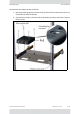
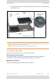


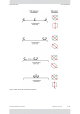


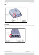
Table Of Contents

FinMInstallationGuide Release4.5.25 2‐47
TMUAntennas SiteInstallation
Figure2‐87:“Shark‐Fin”antenna‐bottomandtopviews
Notethefollowing:
• TheantennasshouldbemountedasclosetotheTMUaspossible.
• Trytominimizeobstructionsbetweentheante nnasandthefrontofthetrainsuchas
air‐conditionerunits,electronicroutenumberdisplayboxesandthelike.
• MountAntenna1andAntenna2ontheedgeofthelocomotiveata45
o
angle,as
showninFigure 2‐88.AlsoseeTMU‐TBSan tennaalternativeorientationoptionson
page 2‐47forotherpossibilities.
• MountAntenna3(center)ata90
o
angle(directlyup)asshowninFigure 2‐88.
• ConnecttheantennaportsoftheTMUtotheantennasasshowninFigure 2‐90.
Figure2‐88:TMUantennamountingconfigurationonroof
TMU‐TBSantennaalternativeorientationoptions
AlthoughFigure 2‐88,"TMUantennamountingconfigurationonroof"showsthemost
commonmethodofmountingtheTMUantennas,thereareotheroptions,andtheseare
shownhere: