
Operating instructions


QAM256 Digital Video Modulator and Upconverter Installation
TM077 – Rev. 4.0 2-1
Installation
2
This section provides unpacking and installation instructions, and a description of external
connections and backward alarm information.
2.0 Installation Requirements
The QAM256 Modem is designed to be installed within any standard 19-inch wide equipment
cabinet or rack, and requires one rack unit (RU) of mounting space (1.75 inches) vertically and
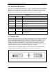
17¾ inches of depth. Including cabling, a minimum of 20 inches of rack depth is required. The
rear panel of the modem is designed to have power enter from the left and IF Cabling enter from
the right when viewed from the rear of the unit. Data and Control Cabling can enter from either
side although they are closer to the center. The unit can be placed on a table or suitable surface
if required.
There are no user-serviceable parts or configuration settings
located inside the QAM256 Chassis. There is a potential shock
hazard internally at the Power Supply Module. DO NOT open the
QAM256 Chassis under any circumstances. Always disconnect the
main plug before servicing of any kind.
Before initially applying power to the unit, it is a good idea to disconnect
the transmit output from the operating ground station equipment. This is
especially true if the current QAM256 configuration settings are
unknown, where incorrect settings could disrupt existing
communications traffic.
2.1 Unpacking
The QAM256 Digital Video Modulator and Upconverter was carefully packaged to avoid damage
and should arrive complete with the following items for proper installation:
QAM256 Unit
Power Cord, with applicable AC Connector
Installation and Operation Manual