
Operating instructions


QAM256 Digital Video Modulator and Upconverter User Interfaces
TM077 – Rev. 4.0 4-3
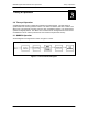
4.1.4 Front Panel LED Indicators
Eight LEDs on the QAM256 Front Panel (Refer to Table 4-3) indicate the status of the QAM256’s
operation. The LED colors maintain a consistent meaning. Green signifies that the indication is
appropriate for normal operation, Yellow means that there is a condition not proper for normal
operation, and Red indicates a fault condition that will result in lost communications.
Table 4-3.
LED Color Function
Transmit On Green Indicates that the QAM256 Transmitter is turned on.
Major Alarm Red Indicates that the transmit direction has failed, losing traffic.
Minor Alarm Yellow Indicates that a transmit receive warning condition exists.
Test Mode Yellow Indicates that the modulator is involved in a current test
mode activity.
Power Green Indicates that the unit is turned on.
Fault Red Indicates a hardware fault for the unit.
Event Yellow Indicates that a condition or event has occurred that the unit
has stored in memory.
Remote Green Indicates that the unit is set to respond to the remote control
or terminal input.
4.2 Parameter Setup
The four Cursor Control Arrow Keys are used to navigate the menu tree and select the parameter
to be set. After arriving at a parameter that needs to be modified, depress <ENTER>. The first
space of the modifiable parameter highlights (blinks) and is ready for a new parameter to be
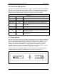
entered. After entering the new parameter using the keypad (Refer to Figure 4-2), depress
<ENTER> to lock in the new parameter. If a change needs to be made prior to pressing
<ENTER>, depress <CLEAR> and the display defaults back to the original parameter. Depress
<ENTER> again and re-enter the new parameters followed by <ENTER>.
Following a valid input, the QAM256 will place the new setting into the nonvolatile EEPROM
making it available immediately and available the next time the unit is powered-up.’
Figure 4-2. Entering New Parameters