
Operating instructions


Remote Operations QAM256 Digital Video Modulator and Upconverter
C-2 TM077 – Rev. 4.0
C.1.2 Protocol Wrapper
The Radyne COMMSPEC is byte-oriented, with the Least Significant Bit (LSB) issued first. Each
data byte is conveyed as mark/space information with two marks comprising the stop data. When
the last byte of data is transmitted, a hold comprises one steady mark (the last stop bit). To begin
or resume data transfer, a space (00h) substitutes this mark. This handling scheme is controlled
by the hardware and is transparent to the user. A basic pictorial representation of the data and its
surrounding overhead may be shown as follows:
S1 S2 B0 B1 B2 B3 B4 B5 B6 B7 S1 S2 Etc.
The stop bits, S1 and S2, are each a mark. Data flow remains in a hold mode until S2 is replaced
by a space. If S2 is followed by a space, it is considered a start bit for the data byte and not part
of the actual data (B0 - B 7).
The COMMSPEC developed for use with the Radyne Link Level Protocol (RLLP) organizes the
actual monitor and control data within a shell, or "protocol wrapper” that surrounds the data. The
format and structure of the COMMSPEC message exchanges are described herein. Decimal
numbers have no suffix; hexadecimal numbers end with a lowercase h suffix and binary values
have a lower case b suffix. Thus, 22 = 16h = 000010110b. The principal elements of a data
frame, in order of occurrence, are summarized as follows:
<SYN> - the message format header character, or ASCII sync character, that defines the
beginning of a message. The <SYN> character value is always 16h.
<BYTE COUNT> - the Byte Count is the number of bytes in the <DATA> field, ranging from zero
through TBD. This field is 2 bytes long for the QAM256 protocol.
<SOURCE ID> - the Source Identifier defines the multi-drop address origin. Note that all nodes
on a given control bus have a unique address that must be defined.
<DESTINATION ID> - The Destination Identifier serves as a pointer to the multi-drop destination
device that indicates where the message is to be sent.
<FRAME SEQUENCE NUMBER> - The FSN is a tag with a value from 0 through 255 that is sent
with each message. It assures sequential information framing and correct equipment
acknowledgment and data transfers.
<OPCODE> - The Operation Code field contains a number that identifies the message type
associated with the data that follows it. Equipment under MCS control recognizes this byte via
firmware identification and subsequently steers the DATA accordingly to perform a specific
function or series of functions. Acknowledgment and error codes are returned in this field. This
field is 2 Bytes for the QAM256 protocol.
<...DATA...> - The Data field contains the binary, bi-directional data bytes associated with the
<OPCODE>. The number of data bytes in this field is indicated by the <BYTE COUNT> value.
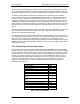
<CHECKSUM> - The checksum is the modulo 256 sum of all preceding message bytes,
excluding the <SYN> character. The checksum determines the presence or absence of errors
within the message. In a message block with the following parameters, the checksum is
computed as shown below in Table 1.