
Operating instructions


Remote Operations QAM256 Digital Video Modulator and Upconverter
C-6 TM077 – Rev. 4.0
advantageous to consider the use of multiple bus systems where warranted by a moderate to
large equipment complement.
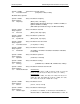
Therefore, if a DMD15 Modulator is queried for its equipment type identifier, it will return a "20"
and DMD15 Demodulator will return a "21". A DMD15 Modem will also return a "22". A DM45
Video Modulator will return a “23.”
C.1.6 Software Compatibility
The COMMSPEC, operating in conjunction within the RLLP shell, provides for full forward and
backward software compatibility independent of the software version in use. New features are
appended to the end of the DATA field without OPCODE changes. Older software simply
discards the data as extraneous information without functional impairment for backward
compatibility.
If new device-resident or M&C software receives a message related to an old software version,
new information and processes are not damaged or affected by the omission of data.
The implementation of forward and backward software compatibility often, but not always,
requires the addition of new Opcodes. Each new function requires a new Opcode assignment if
forward and backward compatibility cannot be attained by other means.
C.1.7 Flow Control and Task Processing
The original packet sender (the M&C computer) relies on accurate timeout information with
regard to each piece of equipment under its control. This provides for efficient bus communication
without unnecessary handshake overhead timing. One critical value is designated the Inter-
Frame Space (FS). The Inter-Frame Space provides a period of time in which the packet receiver
and medium (control bus and M&C computer interface) fully recover from the packet
transmission/reception process and the receiver is ready to accept a new message. The
programmed value of the Inter-Frame Space should be greater than the sum of the "turnaround
time" and the round-trip (sender/receiver/bus) propagation time, including handshake overhead.
The term "turnaround time" refers to the amount of time required for a receiver to be re-enabled
and ready to receive a packet after having just received a packet. In flow control programming,
the Inter-Frame Space may be determined empirically in accord with the system configuration or
calculated based on established maximum equipment task processing times.
Each piece of supported equipment on the control bus executes a Radyne Link Level Task
(RLLT) in accordance with its internal hardware and fixed program structure. In a flow control
example, the RLLT issues an internal "message in" system call to invoke an I/O wait condition
that persists until the task receives a command from the M & C computer. The RLLT has the
option of setting a timeout on the incoming message. Thus, if the equipment does not receive an
information/command packet within a given period, the associated RLLT exits the I/O wait state
and takes appropriate action.
Radyne equipment is logically linked to the control bus via an Internal Input / Output Processing
Task (IOPT) to handle frame sequencing, error checking, and handshaking. The IOPT is
essentially a link between the equipment RLLT and the control bus. Each time the M&C computer
sends a message packet; the IOPT receives the message and performs error checking. If errors
are absent, the IOPT passes the message to the equipment's RLLT. If the IOPT detects errors, it
appends error messages to the packet. Whenever an error occurs, the IOPT notes it and discards
the message; but it keeps track of the incoming packet. Once the packet is complete, the IOPT
conveys the appropriate message to the RLLT and invokes an I/O wait state (wait for next
<SYNC> character).