RAEMesh2 User Manual Doc.
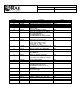
RAEMesh2 User Manual Doc.No: Originator: kren Page 2 of 21 Revision 0.1 0.2 0.3 0.4 0.5 0.6 Date 11/28/2008 12/1/2008 1/4/2009 1/5/2009 3/26/2010 4/22/2010 0.7 5/20/10 0.8 5/25/10 0.9 8//17/10 1.0 10/14/10 1.1 11/19/10 1.2 Comments Initial Add “Radio Core Setting Procedure” Add “Fuse config”, “Firmware programmer” Add “Soft Reset” command Add “Reset reason” command Add description about TXPOWER and Channel setting Add START_ROUTING command.
RAEMesh2 User Manual Doc.No: Originator: kren Page 3 of 21 Data: 2014-3-18 1. Introduction The RAEMesh Radio module offers a complete microcontroller/transceiver solution Containing all hardware features necessary for development of a low data-rate, low-power wireless application. The primary components include an IEEE 802.15.
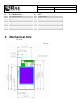
RAEMesh2 User Manual Doc.No: Originator: kren Page 4 of 21 25 27 29 31 33 35 37 39 BUTTON0/GPIO8 BUTTON1/GPIO9 GPIO10 RF_SO RF_SI RF_CK SFD +3.3V 3. Mechanical Size Top View 26 28 30 32 34 36 38 40 AREF ATEMP/ADC1 ADC2 TCK TMS TDO TDI +3.
RAEMesh2 User Manual Doc.No: Originator: kren Page 5 of 21 Data: 2014-3-18 The height of the shielding box is 4.3mm from the PCB. 40 Pin header (1.27mm) is used for board to board connection. Corresponding mate connector can be JVE 22P8702-40M00B-01G-4.5 4. Firmware The module is pre-loaded with the bootloader, which supports serial bootloading of firmware update. The module contains RAEMesh application and comply with the RAE System’s RCS protocol.
RAEMesh2 User Manual Doc.No: Originator: kren Page 6 of 21 Data: 2014-3-18 The Wakeup pin must be held up to 10ms before sending a data packet. Power Ground: Pin1, Pin2 and Pin4. VCC: Pin39, Pin40. 3.0V or 3.3V Heartbeat Connect Pin12 to a LED for heartbeat indicator. Reset. RST: Pin3 Active Low. PC communication Please has your serial port debug software installed on the PC. For example: sscom32.
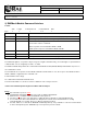
RAEMesh2 User Manual Doc.No: Originator: kren Page 7 of 21 Data: 2014-3-18 TxPwr: Medium PanId: 0x03E5 2) RAEMesh Module Command Interface Format: SOP Byte: Length 1 Command Code 1 Command Data 1 0~n EOP 1 Byte Number Name Comment 0 SOP Radio Protocol beginning of packet. This is always ‘[‘ (0x5B) 1 Length Total length of packet + 0x20, include ‘[‘ and ‘]’. 2 Command Code 0x20 ~ 0xFF. Excluding:0x5A~0x5F and 0x7A~0x7F. 0xF0~0xFF are reserved for common commands.
Table1 RAEMesh and RAEMeshII Difference Item RAEMesh RAEMeshII Hardware MCU: ATMEGA128L Radio: EM2420 Stack Ember Zigbee Stack MCU: ATMEGA1281V Radio: AT86RF212, AT86RF230, AT86RF231 Atmel Bitcloud Specification Zigbee 2004 Zigbee Pro Power Failure Support Un-support RSSI Router/RTR update RSSI when it receive every frame. Support Router/RTR read next hop’s RSSI. EUI Set it on RangeTest. Transmission power Always is maximum. Set it on application firmware.
Command List of RMCI 5B 24 20 5D = Get network status 5B 24 50 5D = Join or form network by scan. 5B xx 26 dd dd 7B .. .. 7D 5D = Send massage in unicast 5B 5B 5B 5B 5B 5B 5B 5B 24 24 24 24 24 24 24 24 2A 3A 60 6C 68 7B 40 4C 5D 5D 5D 5D 5D 5D 5D 5D = = = = = = = = Get Radio Type Get device application type Get Radio's UID, channel, PANID Get Application's UID, channel, PANID Get parent Network ID Get Last Hop Link Quality (LQI) Get reset reason.
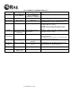
3) Command Sets Command Name Effect CMD Area Code CMD Data (bytes) NETWORK_STATUS RM Use on: RMII GTW RTR STD 0x20 None SEND_MSG_UNI Use on: GTW RTR STD 0x26 DestAdd(2) RCS Pack(x) RM GET_MODULE_TYPE RM Use on: RMII GTW RTR STD Resp onse CMD Code 0x21 Response Data(Bytes) CMD Description STATUS(1) Return the radio’s network status 0x00: NO NETWORK 0x02: JOINED NETWORK. Host controller or instrument should call it periodically with certain duty cycle to check the network status.
GTW_ENABLE Use on: GTW RTR STD RTR_ENABLE Use on: GTW RTR STD CHG_RRCM_CHAN Use on: GTW RTR STD RM RMII 0x30 None 0x31 None 9: RM900A 10: RM2400 11: coRE1-433MHz 12: coRE1-868MHz 13: coRE1-915MHz 14: coRE2-433MHz 15: coRE2-868MHz 16: coRE2-915MHz 17: coRE6-2.4GHz 18: RM2400 19: RM2400M 20: Reserved for 2.
BAND_915_NA. 0x0B to 0x1A total 16 channels for RM2400 if region is BAND_2400_ISM. RPT_LOCATION Use on: GTW RTR STD GET_APPTYPE Use on: GTW RTR STD RM RMII 0x38 None 0x39 None RM RMII 0x3A None 0x3B AppType(1) SET_TX_POWER Use on: GTW RTR STD RM RMII 0x3C TxPwr(1) 0x3D None If channel number is not compliance with radio region, do not return response CMD. Reset automatically. Print node’s network information in ASCII. Get application type.
RST_REASON Use on: GTW RTR STD RM RMII 0x40 None 0x41 Reason(1) CHG_PAN_ID Use on: GTW RTR STD STD_ENABLE Use on: GTW RTR STD SOFT_RESET Use on: GTW RTR STD FACTORY_RST Use on: GTW RTR STD RM RMII 0x44 PanID:(2) XXXX 0x45 None Below just list RAEMeshII reset reason, 0x00 = UNKNOW, 0x01 = RESET_ EXTERNAL, 0x02 = RESET_ POWERON_, 0x03 = RESET_ WDT, 0x04 = RESET_BROWNOUT, 0x05 = RESET_JTAG, 0x06 = RESET_WARM, Change GTW Pan ID into XXXX. From 0x0001 to 0x03E7(1-999) Reset automatically.
GET_FWVERSION Use on: GTW RTR STD RM RMII RW 0x4C None 0x4D Fw Version Time[30] SET_UID Use on: GTW RTR STD RMII 0x4E UID(8) 0x4F None JION_FORM_NETWO RM RK RMII Use on: GTW RTR STD GET_NEIGHBOUR_LI RMII ST Use on: GTW RTR STD 0x50 None 0x51 None and Build Return fw version and build time, for example [BMv1.00 Feb 14 2011 10:11:11], this mean fw version is V1.00 and build is on Feb 14 2011 10:11:11. For RMII: Set radio’s UID(MAC address).
SET_BOOTLOADER RM Use on: RMII GTW RTR STD 0x56 None 0x57 None Make modem into bootloader mode and wait for new app image. SYS_CTRL_SET RMII 0x58 System Control Word, B[3]…B[0] 0x59 00 – failed 01 – success SYS_CTRL_GET RMII 0x5A None 0x5B System Control Word, B[3]…B[0] System Control Word. Bit0: Roaming function, 1 – enable; 0 – disable; Bit1: pending, AES128 security, 1 – enable; 0 – disable; Bit2: Receiver setting of RFD; 1 – always on when idle; 0 – power saving mode; . . .
GET_PARENT_ID Use on: RTR STD RM RMII 0x68 None 0x69 Parent radio ID(8) LAST_HOP_RSSI Use on: RTR STD RM RMII RW 0x7B None 0x7C RSSI(1) SET_RECEIVER Use on: STD RMII 0xA0 00 - Disable 01 - Enable 0xA1 None 0x00 00 00 00 00 00 00 00 means that STD or RTR’s parent is coordinator/gateway. 0x00 00 00 00 00 00 mm nn means STD or RTR’s parent is a RTR which short address is mm nn. 0x00 00 00 00 00 00 ff fe means that STD or RTR do not have parent. Get RSSI percent, the higher, the better.
GET_REGION Use on: GTW RTR STD GET_TRAIL_INFO Use on: GTW RTR STD RMII RW 0xA6 None 0xA7 Region(1) Get modem setting of region. RMII 0xA8 None 0xA9 NWK_INFO[16] Use this command to get modem trail information. BYTE0: modem reset count. This count should be increased if any reset occur.(0~255) BYTE1: reset reason.
GET_CMDBATCH Use on: GTW RTR STD RMII 0xAE None 0xAF 00: Disable 01: Enable Return command batch configuration. Caution: RCM will save corresponding command data of AT command into its persist data server if this command cause “Reset automatically”, it will take effect after reset.
4) RMII Command Classification There are a lot of RMCI command set in this manual, different application need different command, below is a table that which command must have, which are recommend and which are optional.
5. Terms GTW: A RTR used for gateway. Only one GTW per network. RTR: Full Function Device. Sensor node with routing ability. RTR requires line power all time. STD: Reduce Function Device. A Sleeping node can only talk to a RTR or GTW. Can not relay the message. Can be a battery powered device. RCM :Radio Communications Module RDTE: Reader Data Terminal Equipment. RMCI: RAEMesh Module Command Interface. SDTE : Sensor Data Terminal Equipment. 6. Reference Atmel: FCC: www.gcc.gov Zigbee Alliance: www.zigbee.
This equipment has been tested and found to comply with the limits for a Class B digital device, pursuant to part 15 of the FCC Rules. These limits are designed to provide reasonable protection against harmful interference in a residential installation. This equipment generates uses and can radiate radio frequency energy and, if not installed and used in accordance with the instructions, may cause harmful interference to radio communications.