Revision: June 2, 2011 RAEMesh Radio User Manual (for RM2400, RM900…) RAE Systems Inc
Revision: June 2, 2011 Introduction The RAEMesh Radio module offers a complete microcontroller/transceiver solution Containing all hardware features necessary for development of a low data-rate, low-power wireless application. The primary components include an IEEE 802.15.4 compliant Zigbee-ready transceiver , a microcontroller, a 40-pin interface connector, a MMCS antenna connector, This documentation describes the RAEMesh radio module hardware interface as well as RAE System’s Command Interface.
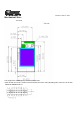
Revision: June 2, 2011 Mechanical Size: Top View The height of the shielding box is 4.3mm from the PCB. 40 Pin header (1.27mm) is used for board to board connection. Corresponding mate connector can be JVE 22P8702-40M00B-01G-4.
Revision: June 2, 2011 Pin Layout Pin 1 3 5 7 9 11 13 15 17 19 21 23 25 27 29 31 33 35 37 39 Description DGND nRESET TXD1 RXD1 GPIO0 GPIO1 GPIO2 GPIO3 TEMP_E/GPIO4 WakeUp/GPIO5 BUZZER/GPIO6 GPIO7/PS_DIR BUTTON0/GPIO8 BUTTON1/GPIO9 GPIO10 RF_SO RF_SI RF_CK SFD +3.3V Pin 2 4 6 8 10 12 14 16 18 20 22 24 26 28 30 32 34 36 38 40 Description DGND DGND TXD0/Bootload. RXD0 GPIO/LED2 GPIO/LED3 GPIO/LED4 GPIO/LED5 GPIO/PS_CS GPIO/PS_FRAME +3.3V AGND AREF ATEMP/ADC1 ADC2 TCK TMS TDO TDI +3.
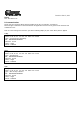
Revision: June 2, 2011 Firmware Description The module is pre-loaded with the bootloader, which supports serial bootloading of firmware update. The module contains RAEMesh application and comply with the RAE System’s RCS protocol. The module also has built-in RAEMesh Module Command Interface(RMCI). This documentation is focused on the instruction on RMCI interface. The RMCI command interface allows customer to easily access to low level mesh functionality without pain to develop the firmware.
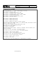
Revision: June 2, 2011 Reset. RST: Pin3 Active Low. PC communication Please has your serial port debug software installed on the PC. For example: sscom32.exe Microsoft Hyper Terminal is not recommended for this application because it is not good to send characters and commands in Hex. Base on correct setting and connection, you will see following display on your screen when power is applied. GTW: [%A ]RAEMESH-II RM2400A 8MHz FwVer:1.10.0.
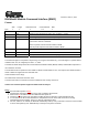
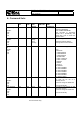
Revision: June 2, 2011 RAEMesh2 Module Command Interface (RMCI) Format: SOP Byte: Length 1 Command Code 1 Command Data 1 0~n EOP 1 Byte Number Name Comment 0 SOP Radio Protocol beginning of packet. This is always ‘[‘ (0x5B) 1 Length Total length of packet + 0x20, include ‘[‘ and ‘]’. 2 Command Code 0x20 ~ 0xFF. Excluding:0x5A~0x5F and 0x7A~0x7F. 0xF0~0xFF are reserved for common commands. Even for packet sent from SDTE or RDTE to RCM. Odd for packet response from RCM to SDTE or RDTE.
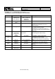
RAEMesh2 RMCI Protocol Doc.No. 904-E800-316 Rev.No. A Date: 10/14/10 Page 8 of 9 RAEMesh and RAEMeshII Difference Item RAEMesh RAEMeshII Hardware MCU: ATMEGA128L Radio: EM2420 Stack Specification Ember Zigbee Stack Zigbee 2004 MCU: ATMEGA1281V Radio: AT86RF212, AT86RF230, AT86RF231 Atmel Bitcloud Power Failure Support RSSI Router/RTR update RSSI when it receive every frame. Support Many-to-one routing(MTOR) EUI Zigbee Pro Un-support Router/RTR read next hop’s RSSI.
RAEMesh2 RMCI Protocol Doc.No. 904-E800-316 Rev.No. A Date: 10/14/10 Page 9 of 9 Command List of RMCI 5B 5B 5B 5B 5B 5B 5B 5B 5B 24 xx 24 24 24 24 24 24 24 20 26 2A 3A 60 6C 68 7B 40 5D dd 5D 5D 5D 5D 5D 5D 5D = Get dd 7B = Get = Get = Get = Get = Get = Get = Get network status .. .. 7D 5D = Send massage in unicast Radio Type device application type Radio's UID, channel, PANID Application's UID, channel, PANID parent Network ID Last Hop Link Quality (LQI) reset reason.
RAEMesh2 RMCI Protocol Doc.No. 904-E800-316 Rev.No.
N Use on: GTW RTR STD RAEMesh2 RMCI Protocol Doc.No. 904-E800-316 Rev.No. A Date: 10/14/10 Page 11 of 9 Number (1) to specified channel. Meanwhile, specified channel should be compliance with radio region setting. 0x00 for RM900 if region is BAND_868_EU. 0x01 to 0x0A total 10 channels for RM900 if region is BAND_915_NA. 0x0B to 0x1A total 16 channels for RM2400 if region is BAND_2400_ISM.
RST_REASON Use on: GTW RTR STD Both SET_ROUTEINTER RAEMeshII VAL Use On: RTR RAEMesh2 RMCI Protocol Doc.No. 904-E800-316 Rev.No.
SET_RECEIVER Use on: STD RAEMeshII 0xA0 RAEMesh2 RMCI Protocol Doc.No. 904-E800-316 Rev.No. A Date: 10/14/10 Page 13 of 9 00 Disable 01 Enable 0xA1 None Enable or disable STD’s receiver. STD should receive data packet from parent if enable receiver; STD should use poll to request data packet from parent if disable receiver. GET_RECEIVER Use on: STD RAEMeshII 0xA2 None 0xA3 Status(1) SET_REGION Use on: GTW RTR STD RAEMeshII 0xA4 Region( 1) 0xA5 None Reset automatically.
GTW RTR STD GET_APPNODE_I Both NFO Use on: GTW RTR STD GET_PARENT_ID Both Use on: RTR STD RAEMesh2 RMCI Protocol Doc.No. 904-E800-316 Rev.No.
RAEMesh2 RMCI Protocol Doc.No. 904-E800-316 Rev.No. A Date: 10/14/10 Page 15 of 9 Caution: RCM will save corresponding command data of AT command into its persist data server if this command cause “Reset automatically”, it will take effect after reset.
RAEMesh2 RMCI Protocol Doc.No. 904-E800-316 Rev.No. A Date: 10/14/10 Page 16 of 9 Procedure for Radio Core Setting: A. Configure ATMega1281 Fuse. Software: AVRUSB V2.0.2.231, Hardware: AVRUSB ISP on M3 Eva Board. 1. Make sure the correct hardware selected 2. Click “Reset”, make sure the AVRUSB connected to target 3.
RAEMesh2 RMCI Protocol Doc.No. 904-E800-316 Rev.No. A Date: 10/14/10 Page 17 of 9 4.
RAEMesh2 RMCI Protocol Doc.No. 904-E800-316 Rev.No. A Date: 10/14/10 Page 18 of 9 5.
RAEMesh2 RMCI Protocol Doc.No. 904-E800-316 Rev.No.
RAEMesh2 RMCI Protocol Doc.No. 904-E800-316 Rev.No. A Date: 10/14/10 Page 20 of 9 B. Firmware Program. Software ZigBit Firmware Programmer V1.32 1. Select firmware file, *.srec 2. Select correct com port 3. Click “Program”, then Reset RAEMesh2 module in 30 seconds 4. Waiting for program successful. C. Configure RAEMesh2 Application. Software SSCOM32.exe, RMCI. 1. Set UID/MAC address 5B 2C 4E xx xx xx xx xx xx xx xx 5D Note: The last two bytes must not set to 0x0000 ~ 0x0010, 0xFFF0-0xFFFF 2.
RAEMesh2 RMCI Protocol Doc.No. 904-E800-316 Rev.No. A Date: 10/14/10 Page 21 of 9 Terms: GTW: A RTR used for gateway. Only one GTW per network. RTR: Full Function Device. Sensor node with routing ability. RTR requires line power all time. STD: Reduce Function Device. A Sleeping node can only talk to a RTR or GTW. Can not relay the message. Can be a battery powered device. RCM :Radio Communications Module RDTE: Reader Data Terminal Equipment. RMCI: RAEMesh Module Command Interface.