RAEMesh2 User Manual Doc.
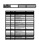
RAEMesh2 User Manual Doc.No: Originator: kren Page 2 of 38 Revision 0.1 0.2 0.3 0.4 0.5 0.6 Date 11/28/2008 12/1/2008 1/4/2009 1/5/2009 3/26/2010 4/22/2010 0.7 5/20/10 0.8 5/25/10 0.9 8//17/10 1.0 10/14/10 1.1 11/19/10 1.2 Comments Initial Add “Radio Core Setting Procedure” Add “Fuse config”, “Firmware programmer” Add “Soft Reset” command Add “Reset reason” command Add description about TXPOWER and Channel setting Add START_ROUTING command.
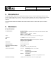
RAEMesh2 User Manual Doc.No: Originator: kren Page 3 of 38 Data: 2014-3-18 1. Introduction The RAEMesh Radio module offers a complete microcontroller/transceiver solution Containing all hardware features necessary for development of a low data-rate, low-power wireless application. The primary components include an IEEE 802.15.
RAEMesh2 User Manual Doc.No: Originator: kren Page 4 of 38 2) Pin Layout Pin 1 3 5 7 9 11 13 15 17 19 21 23 25 27 29 31 33 35 37 39 Description DGND nRESET TXD1 RXD1 GPIO0 GPIO1 GPIO2 GPIO3 TEMP_E/GPIO4 WakeUp/GPIO5 BUZZER/GPIO6 GPIO7/PS_DIR BUTTON0/GPIO8 BUTTON1/GPIO9 GPIO10 RF_SO RF_SI RF_CK SFD +3.3V Pin 2 4 6 8 10 12 14 16 18 20 22 24 26 28 30 32 34 36 38 40 Description DGND DGND TXD0/Bootload. RXD0 GPIO/LED2 GPIO/LED3 GPIO/LED4 GPIO/LED5 GPIO/PS_CS GPIO/PS_FRAME +3.
RAEMesh2 User Manual Doc.No: Originator: kren Page 5 of 38 Data: 2014-3-18 3. Mechanical Size Top View The height of the shielding box is 4.3mm from the PCB. 40 Pin header (1.27mm) is used for board to board connection. Corresponding mate connector can be JVE 22P8702-40M00B-01G-4.
RAEMesh2 User Manual Doc.No: Originator: kren Page 6 of 38 Data: 2014-3-18 4. Firmware The module is pre-loaded with the bootloader, which supports serial bootloading of firmware update. The module contains RAEMesh application and comply with the RAE System’s RCS protocol. The module also has built-in RAEMesh Module Command Interface(RMCI). This documentation is focused on the instruction on RMCI interface.
RAEMesh2 User Manual Doc.No: Originator: kren Page 7 of 38 Data: 2014-3-18 Reset. RST: Pin3 Active Low. PC communication Please has your serial port debug software installed on the PC. For example: sscom32.exe Microsoft Hyper Terminal is not recommended for this application because it is not good to send characters and commands in Hex. Base on correct setting and connection, you will see following display on your screen when power is applied. GTW: [%AĂ]RAEMESH-II RM2400A 8MHz FwVer:V1.
RAEMesh2 User Manual Doc.No: Originator: kren Page 8 of 38 Data: 2014-3-18 2) RAEMesh Module Command Interface Format: SOP Byte: Length 1 Command Code 1 Command Data 1 0~n EOP 1 Byte Number Name Comment 0 SOP Radio Protocol beginning of packet. This is always ‘[‘ (0x5B) 1 Length Total length of packet + 0x20, include ‘[‘ and ‘]’. 2 Command Code 0x20 ~ 0xFF. Excluding:0x5A~0x5F and 0x7A~0x7F. 0xF0~0xFF are reserved for common commands. Even for packet sent from SDTE or RDTE to RCM.
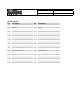
Table1 RAEMesh and RAEMeshII Difference Item RAEMesh RAEMeshII Hardware MCU: ATMEGA128L Radio: EM2420 Stack Ember Zigbee Stack MCU: ATMEGA1281V Radio: AT86RF212, AT86RF230, AT86RF231 Atmel Bitcloud Specification Zigbee 2004 Zigbee Pro Power Failure Support Un-support RSSI Router/RTR update RSSI when it receive every frame. Support Router/RTR read next hop’s RSSI. EUI Set it on RangeTest. Transmission power Always is maximum. Set it on application firmware.
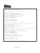
Command List of RMCI 5B 24 20 5D = Get network status 5B 24 50 5D = Join or form network by scan. 5B xx 26 dd dd 7B .. .. 7D 5D = Send massage in unicast 5B 5B 5B 5B 5B 5B 5B 5B 24 24 24 24 24 24 24 24 2A 3A 60 6C 68 7B 40 4C 5D 5D 5D 5D 5D 5D 5D 5D = = = = = = = = Get Radio Type Get device application type Get Radio's UID, channel, PANID Get Application's UID, channel, PANID Get parent Network ID Get Last Hop Link Quality (LQI) Get reset reason.
GET_MODULE_TYPE RM Use on: RMII GTW RTR STD 0x2A 0x26 SEND_MSG_UNI Use on: GTW RTR STD RM 0x20 Effect CMD Area Code NETWORK_STATUS RM Use on: RMII GTW RTR STD Command Name 3) Command Sets For Internal Use Only None DestAdd(2) RCS Pack(x) None CMD Data (bytes) 0x2B 0x27 Resp onse CMD Code 0x21 Type(1) None STATUS(1) Response Data(Bytes) CMD RCS Pack(x) must be compliant with RCS format. Return the radio’s type.
Use on: GTW RTR STD CHG_RRCM_CHAN Use on: GTW RTR STD Use on: GTW RTR STD RTR_ENABLE GTW_ENABLE RM RMII RM RMII RM RMII 0x34 0x32 0x30 For Internal Use Only Channel Number(1) None None 0x35 0x33 0x31 None None None 0x01 to 0x0A total 10 channels for RM900 if region is 0x00 for RM900 if region is BAND_868_EU. Requests change radio channel to specified channel. Meanwhile, specified channel should be compliance with radio region setting. Reset automatically. Set radio to RTR.
0x3A 0x3C RM RMII RM RMII RM RMII SET_TX_POWER Use on: GTW RTR STD LEAVE_NETWORK Use on: GTW RTR STD 0x3E 0x38 RM RMII RPT_LOCATION Use on: GTW RTR STD GET_APPTYPE Use on: GTW RTR STD For Internal Use Only None TxPwr(1) None None 0x3F 0x3D 0x3B 0x39 None None AppType(1) None Reset automatically. Leave the current network. For RAEMesh Power setting from 0xE3(-25dBm) to 0xFF(0dBm). Get application type.
0x44 0x46 0x48 0x4A RM RMII RM RMII RM RMII RM RMII CHG_PAN_ID Use on: GTW RTR STD STD_ENABLE Use on: GTW RTR STD SOFT_RESET Use on: GTW RTR STD FACTORY_RST Use on: GTW RTR STD 0x40 RM RMII RST_REASON Use on: GTW RTR STD For Internal Use Only None None None PanID:(2) XXXX None 0x4B 0x49 0x47 0x45 0x41 None None None None Reason(1) Reset automatically. Restore the RCM to factory defaults.
None None 0x50 0x54 JION_FORM_NETWO RM RK RMII Use on: GTW RTR STD GET_NEIGHBOUR_LI RMII ST Use on: GTW RTR STD For Internal Use Only UID(8) 0x4E RMII None SET_UID Use on: GTW RTR STD 0x4C RM RMII RW GET_FWVERSION Use on: GTW RTR STD 0x55 0x51 0x4F 0x4D and Node[0] shortAddr[2] rssi[1] relation[1] depth[1] Node[1]… Node[2]… … None None Fw Version Time[30] Build Neighbor table list like this: shortAddr: Short address when network is up.
0x58 0x60 0x6C RMII RMII RMII RM RMII RM RMII SYS_CTRL_SET SYS_CTRL_GET SEC_KEY_SET GET_NODE_INFO Use on: GTW RTR STD GET_APPNODE_INF O Use on: GTW RTR STD 0x5C 0x5A 0x56 SET_BOOTLOADER RM Use on: RMII GTW RTR STD For Internal Use Only None None KEY[15]…KEY[0] None System Control Word, B[3]…B[0] None 0x6D 0x61 0x5D 0x5B 0x59 0x57 UID(8) Channel(1) Power(1) PAN ID(2) UID(8) Channel(1) Power(1) PAN ID(2) 00- failed 01- success System Control Word, B[3]…B[0] 00 – failed 01 – su
0x68 0x7B 0xA0 0xA2 0xA4 RM RMII RM RMII RW RMII RMII RMII GET_PARENT_ID Use on: RTR STD LAST_HOP_RSSI Use on: RTR STD SET_RECEIVER Use on: STD GET_RECEIVER Use on: STD SET_REGION Use on: GTW RTR STD For Internal Use Only Region(1) None 00 - Disable 01 - Enable None None 0xA5 0xA3 0xA1 0x7C 0x69 None Status(1) None RSSI(1) Parent radio ID(8) Reset automatically.
0xA8 0xFE 0xAC RMII SET_DEBUG_PRINT RM Use on: RMII GTW RTR STD RMII SET_CMDBATCH Use on: GTW RTR STD 0xA6 RMII RW GET_REGION Use on: GTW RTR STD GET_TRAIL_INFO Use on: GTW RTR STD For Internal Use Only 00, Disable 01, Enable 00,Disable 01,Enable None None 0xAD 0xFF 0xA9 0xA7 None None NWK_INFO[16] Region(1) Enable or disable command batch function. If enable, modem will not reset automatically after change panid, channel, power, eui, regionˈ receiver and join permission.
RMII 0xAE None 0xAF 00: Disable 01: Enable Return command batch configuration. For Internal Use Only Caution: RCM will save corresponding command data of AT command into its persist data server if this command cause “Reset automatically”, it will take effect after reset.
4) RMII Command Classification There are a lot of RMCI command set in this manual, different application need different command, below is a table that which command must have, which are recommend and which are optional.
5. Bootloader Bootloader is a stand-alone utility consisting of two parts: embedded bootstrap code that should be loaded to the flash memory of a supported MCU and the PC based application that sends data to the embedded bootstrap over serial link. Embedded bootstrap code uses the received data to program the internal flash memory of the MCU. A simple communication protocol is used to ensure proper programming. RAEMeshII have two types of bootloader, one is from Atmel, the other is from REC.
If there is not any phenomenon on LED1 and USART after reset modem, this modem embed Atmel bootloader. b) Bootloader and application mixed If modem have bootloader and application in corresponding flash memory, using above method is useless. We can use SET_BOOTLOADER(0x5B 24 56 5D) to distinguish. First, send SET_BOOTLOADER through USART port to modem. Then, if modem reset and print startup menu of application as below, this modem embed Atmel bootloader.
2) How to embed RAELoader_ATMega1281 If you want to embed bootloader into RM900 or RM2400A which use ATMega1281 as mcu, no matter Atmel bootloader or RAELoader, you should prepare corresponding tool. Software: AVRUSB V2.0.2.231 Hardware: AVRUSB Programmer and RAEMeshII Dev board. Then, operate step by step as below, a) Make sure the correct hardware selected b) Make sure the AVRUSB connected to dev board and board is power on, click “Reset”.
c) Erase target MCU d) Read out current fuse setting. If you want to embed Atmel bootloader, please go to Step e). If you want to embed RAELoader, please go to Step f).
e) Check the following setting, it’s used for Atmel bootloader For Internal Use Only
f) Check the following settings and make sure as same as showed. Caution: RAELoader ATmega1281’s Boot Block Size should be 4096 bytes.
g) Write back Fuse setting if any changes made, make sure program successfully. If you want to embed Atmel bootloader, please go to Step h). If you want to embed RAELoader, please go to Step i).
h) Load ATMEL bootloader hex image. Find corresponding path and load *.hex which should be written into boot flash memory. i) Load RAELoader hex image. Find corresponding path and load *.hex which should be written into flash merory.
j) Press Device -> Program -> Flash, load bootloader image successfully.
3) How to embed RAELoader_Sam7x If you want to embed bootloader into RM900A which use AT91SAM7X256 as mcu, you should prepare corresponding tool. Software: SEGGER J-Flash ARM V4.20 Hardware: JLINK ARM Programmer and RAEMeshII Dev board.
b) click “CPU” and choose AT91SAM7X256 as device. c) put RM900A on dev board and use JLINK to connect with it. d) click “File” ->”Open data file” to choose RAELoader_Sam7x *.hex file.
e) click “Target” -> “Erase chip” to erase all flash memory. f) click “Target” -> “Program” to downloader RAELoader hex file into mcu.
g) click “Target” -> “Start application” to make mcu run. h) Then, embed RAELoader_Sam7x is successful, go to Section4. 4) Firmware Upgrade User should use different utility to upgrade RAEMeshII application firmware. a) Using Atmel bootloader to upgrade 1. Select firmware file, *.srec 2. Select correct com port 3. Click “Program”, then Reset RAEMesh2 module in 30 seconds Waiting for program successful.
b) Using RAELoader to upgrade 1. Use RMCI command to access RAELoader If modem run app firmware, we can use RMCI command, 0x5b 24 56 5d, to access RAELoader for firmware upgrade. 2. Use jumper to access RAELoader We can use hardware jumper to access RAELoader. First, jump specified pin to ground; second, press reset button on evaluation board to reset modem; then modem access into RAELoader.
Now, we have two type of evaluation board, please use following method for loader jumper. Old evaluation board setup, it is the same with how to set ZcoRAE-M3 into bootloader.
3. RAELoader Indication RAELoader use LEDs blink and toggle on M3 adapter or evaluation board to tell user the situation of loader. When modem access into RAELoader, one LED, which lable is LED2 on M3 adapter, will blink continuously. If start to upgrade firmware, two LEDs on evaluation board will blink continuously and alternately. 4. Upgrade When modem is in RAELoader, we use RAEProgrammer4000 to upgrade firmware, detail please refer to user guide of RAEProgrammer4000. 5.
6. Terms GTW: A RTR used for gateway. Only one GTW per network. RTR: Full Function Device. Sensor node with routing ability. RTR requires line power all time. STD: Reduce Function Device. A Sleeping node can only talk to a RTR or GTW. Can not relay the message. Can be a battery powered device. RCM :Radio Communications Module RDTE: Reader Data Terminal Equipment. RMCI: RAEMesh Module Command Interface. SDTE : Sensor Data Terminal Equipment. 7. Reference Atmel: FCC: www.gcc.gov Zigbee Alliance: www.zigbee.
could void the user’s authority to operate the equipment. This device must be operated as supplied by Raesystems. Any changes or modifications made to the device can be jeopardize, but there is one exception. The radio’s antenna can be replaced as long as the specification of the antenna matches the original. This equipment has been tested and found to comply with the limits for a Class B digital device, pursuant to part 15 of the FCC Rules.