Revision: Dec, 2011 RAEMesh Radio User Manual (for RM2400, RM900, RM900A…) RAE Systems Inc
Revision: Dec, 2011 Introduction The RAEMesh Radio module offers a complete microcontroller/transceiver solution Containing all hardware features necessary for development of a low data-rate, low-power wireless application. The primary components include an IEEE 802.15.4 compliant Zigbee-ready transceiver , a microcontroller, a 40-pin interface connector, a MMCS antenna connector, This documentation describes the RAEMesh radio module hardware interface as well as RAE System’s Command Interface.
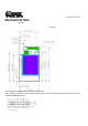
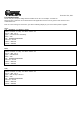
Revision: Dec, 2011 Mechanical Size Top View The height of the shielding box is 4.3mm from the PCB. 40 Pin header (1.27mm) is used for board to board connection. Corresponding mate connector can be JVE 22P8702-40M00B-01G-4.
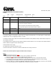
Revision: Dec, 2011 Pin Layout Pin 1 3 5 7 9 11 13 15 17 19 21 23 25 27 29 31 33 35 37 39 Description DGND nRESET TXD1 RXD1 GPIO0 GPIO1 GPIO2 GPIO3 TEMP_E/GPIO4 WakeUp/GPIO5 BUZZER/GPIO6 GPIO7/PS_DIR BUTTON0/GPIO8 BUTTON1/GPIO9 GPIO10 RF_SO RF_SI RF_CK SFD +3.3V Pin 2 4 6 8 10 12 14 16 18 20 22 24 26 28 30 32 34 36 38 40 Description DGND DGND TXD0/Bootload. RXD0 GPIO/LED2 GPIO/LED3 GPIO/LED4 GPIO/LED5 GPIO/PS_CS GPIO/PS_FRAME +3.3V AGND AREF ATEMP/ADC1 ADC2 TCK TMS TDO TDI +3.
Revision: Dec, 2011 Firmware The module is pre-loaded with the bootloader, which supports serial bootloading of firmware update. The module contains RAEMesh application and comply with the RAE System’s RCS protocol. The module also has built-in RAEMesh Module Command Interface(RMCI). This documentation is focused on the instruction on RMCI interface. The RMCI command interface allows customer to easily access to low level mesh functionality without pain to develop the firmware.
Revision: Dec, 2011 PC communication Please has your serial port debug software installed on the PC. For example: sscom32.exe Microsoft Hyper Terminal is not recommended for this application because it is not good to send characters and commands in Hex. Base on correct setting and connection, you will see following display on your screen when power is applied. GTW: [%A ]RAEMESH-II RM900A 16MHz FwVer:V1.02b on Sep 28 2011 09:52:14 Stack: BC1.10.
Revision: Dec, 2011 RAEMesh2 Module Command Interface Format: SOP Byte: Length 1 Command Code 1 Command Data 1 0~n EOP 1 Byte Number Name Comment 0 SOP Radio Protocol beginning of packet. This is always ‘[‘ (0x5B) 1 Length Total length of packet + 0x20, include ‘[‘ and ‘]’. 2 Command Code 0x20 ~ 0xFF. Excluding:0x5A~0x5F and 0x7A~0x7F. 0xF0~0xFF are reserved for common commands. Even for packet sent from SDTE or RDTE to RCM. Odd for packet response from RCM to SDTE or RDTE.
Command List of RMCI 5B 24 20 5D = Get network status 5B 24 50 5D = Join or form network by scan. 5B xx 26 dd dd 7B .. .. 7D 5D = Send massage in unicast 5B 5B 5B 5B 5B 5B 5B 5B 24 24 24 24 24 24 24 24 2A 3A 60 6C 68 7B 40 4C 5D 5D 5D 5D 5D 5D 5D 5D = = = = = = = = Get Radio Type Get device application type Get Radio's UID, channel, PANID Get Application's UID, channel, PANID Get parent Network ID Get Last Hop Link Quality (LQI) Get reset reason.
• Command Sets Command Name Effect Area CMD Code CMD Data (bytes) None Response CMD Code 0x21 Response CMD Data(Bytes) STATUS(1) DestNw kID(2) RCS Pack(x) 0x27 None None 0x2B NETWORK_STATU Both S Use on: GTW RTR STD 0x20 SEND_MSG_UNI RM Use on: GTW RTR STD GET_MODULE_TY Both PE Use on: GTW RTR STD 0x26 GTW_ENABLE Both 0x30 None 0x31 None Use on: GTW RTR STD RTR_ENABLE Both 0x32 None 0x33 None Use on: GTW RTR STD CHG_RRCM_CHA Both N Use on: GTW RTR 0x2A Description Return the ra
STD 0x00 for RM900 if region is BAND_868_EU. 0x01 to 0x0A total 10 channels for RM900 if region is BAND_915_NA. 0x0B to 0x1A total 16 channels for RM2400 if region is BAND_2400_ISM.
SET_ROUTEINTER RMII VAL Use On: RTR CHG_PAN_ID Use on: GTW RTR STD STD_ENABLE Use on: GTW RTR STD SOFT_RESET Use on: GTW RTR STD FACTORY_RST Use on: GTW RTR STD SET_RECEIVER Use on: STD Both 0x42 0x44 Type(1) Interval( 1) PanID:( 2) XXXX 0x43 0x45 None None Type(1) Bit7~bit2: reverse, Bit1: enable route discovery immediately if set, Bit0: set route discovery interval with the value of Interval(1). Interval(1) Routing interval, range is from 10 to 240, unit is second.
GET_RECEIVER Use on: STD SET_REGION Use on: GTW RTR STD RAEMeshII 0xA2 None 0xA3 Status(1) RAEMeshII 0xA4 Region( 1) 0xA5 None GET_REGION RAEMeshII Use on: GTW RTR STD SET_UID RAEMeshII Use on: GTW RTR STD JION_FORM_NET Both WORK Use on: GTW RTR STD GET_ROUTEINTE RVAL Use on: RTR GET_NODE_INFO Use on: GTW RTR STD GET_APPNODE_I NFO Use on: GTW RTR STD GET_PARENT_ID Use on: RTR STD 0xA6 None 0xA7 Region(1) 0x4E UID(8) 0x4F None 0x50 None 0x51 None Return STD receiver’s status, 00 – Dis
nn. 0x00 00 00 00 00 00 ff fe means that STD or RTR do not have parent. Get RSSI percent, the higher, the better. Best: 240 Worst:0 RTR get next hop rssi; STD get parent rssi. Set display debug information enable/disable. The default setting is disabled.
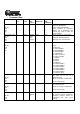
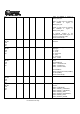
• RMII Command Classification There are a lot of RMCI command set in this manual, different application need different command, below is a table that which command must have, which are recommend and which are optional.
Procedure for Radio Core Setting: A. Configure Software: AVRUSB V2.0.2.231 Hardware: AVRUSB Programmer and RAEMeshII Dev board. 1. Make sure the correct hardware selected 2. Click “Reset”. If a green label is at bottom of AVRUSB framework, go to next step.
3. Erase target MCU 4.
5. Check the following setting.
6. Write back Fuse setting if any changes made, make sure program successfully. B. Firmware Upgrade 1. Select firmware file, *.srec 2. Select correct com port 3. Click “Program”, then Reset RAEMesh2 module in 30 seconds 4.
Terms GTW: A RTR used for gateway. Only one GTW per network. RTR: Full Function Device. Sensor node with routing ability. RTR requires line power all time. STD: Reduce Function Device. A Sleeping node can only talk to a RTR or GTW. Can not relay the message. Can be a battery powered device. RCM :Radio Communications Module RDTE: Reader Data Terminal Equipment. RMCI: RAEMesh Module Command Interface. SDTE : Sensor Data Terminal Equipment. Reference Atmel: www.atmel.com FCC: www.gcc.gov Zigbee Alliance: www.
Label information to the End User by the OEM or integrator If the FCC ID of this module is not visible when it is installed inside another device, then the outside of the device into which the module is installed must be labeled with “Contains FCC ID: SU3RM900A” in a visible area. This equipment has been tested and found to comply with the limits for a Class B digital device, pursuant to part 15 of the FCC Rules.