
User's Manual

Honeywell Confidential and Proprietary Revision –1.1 Page 10 of 15
Copyright © 2015 Honeywell Analytics, All rights reserved.
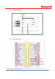
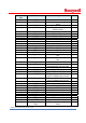
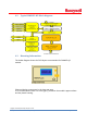
4.2 TypicalRMWIFI‐M5Blockdiagram:
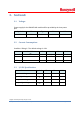
4.3 MountingInformation:
The below diagram shows the PCB layout recommended for RMWIFI-QC
module.
Please minimize components in the keep-out area.
It is recommended to have a 0.4 mm gap (T) between the module's upper surface
and the plastic housing.