User Manual Version : 1.
Introduction SR7650-4S-U3D Quick Installation Guide About this Manual 1. Package Contents Thank you for using the product of RAIDON Technology Inc. This user manual will introduce the STARDOM SCSI series products and will also give you a brief understanding of how the RAID operates. The information in the manual has been thoroughly checked before publication, but may not conform to the product actually delivered. Actual product specifications depend on the product shipped to you.
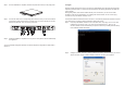
Step 4 Once the installation is completed, insert the tray back and fix it firmly in the proper place. 3. Login SR7650-4S-U3D supports three types of connection for administration login: Web GUI, RS232 and SSH, respectively. Refer to section 2.3 in the user manual for details. The following descriptions use Web GUI as the example: Before getting started, make sure the related network port is connected.
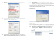
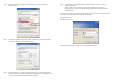
Step 3 Select “Internet Protocol (TCP/IP)” and click “Properties”. A window for IP address settings will pop up. Step 6 Login the system. The default IP address of SR7650-4S-U3D is 192.168.0.1. Open your web browser and input: http://192.168.0.1 or https://192.168.0.1 (using Secure Sockets Layer connection to transfer data with encryption.
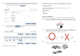
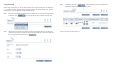
Step 2 Select an ID for each device and avoid ID conflict in the same SCSI bus. You can change the volume size in this page. The maximum volume size will be displayed. Please enter a value less than or equal to that value and then click “ ”. SR5650-4S-U3D Quick Installation Guide 1. Package Contents After you open the outer package, make sure that the following items are in the box: • SR5650-4S-U3D product body • AC Power Cord • RS-232 Port Cable • CD • User Manual • Accessory Kit 2.
Step 4 Once the installation is completed, insert the tray back and fix it firmly in the proper place. 3. Login SR7650-4S-U3D supports three types of connection for administration login: Web GUI, RS232 and SSH, respectively. Refer to section 2.3 in the user manual for details. The following descriptions use Web GUI as the example: Before getting started, make sure the related network port is connected.
Step 3 Select “Internet Protocol (TCP/IP)” and click “Properties”. A window for IP address settings will pop up. Step 6 Login the system. The default IP address of SR5650-4S-U3D is 192.168.0.1. Open your web browser and input: http://192.168.0.1 or https://192.168.0.1 (using Secure Sockets Layer connection to transfer data with encryption.
4. System Setup Step 3 ” if all the settings are correct user data volume Confirmation page. Click “ created will be displayed as shown by the figure below. After the login to the system, you can use “Quick install” function for quick configuration. On RAID levels 0, 1, 3, 5 and 6, the system will automatically calculate the maximum available capacity, which is subject to the number of your hard disks and currently available capacity. Step 1 Select “Quick install” and then select a RAID level.
Contents Chapter 1 1.1. 1.2. 1.3. 1.4. 1.5. Chapter 2 2.1 2.1.1. 2.1.2. 2.1.3. 2.2 2.2.1. 2.3 2.3.1 2.3.2 2.3.3 2.4 2.4.1 2.4.2 2.4.3 Chapter 3 3.1 3.2 3.3 3.4 3.4.1 3.4.2 3.4.3 3.4.4 3.4.5 3.4.6 3.4.7 3.4.8 3.4.9 3.5 3.5.1 3.5.2 3.5.3 3.5.4 3.5.5 3.5.6 3.5.7 3.6 3.6.1 3.6.2 3.6.3 RAID Introduction.................................................................... 18 What is RAID?.................................................................................................... RAID Functions..........
Chapter 1 1.1.
Chapter 2 2.1 Installation Notice Before Installation 2.1.1. STARDOM SCSI Series Products Features STARDOM SCSI Series Products with the features as follows: • Dual SCSI channels design • 4 eSATA expansion interfaces • Supports RAID 6 level • Supports hot-swap • N-way mirroring • GUI operator interface • Online capacity expansion and RAID level conversion • Volume-specific shared/dedicated cache • Supports S.M.A.R.T • Supports SAF-TE • Array roaming 2.1.3.
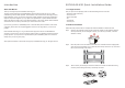
Step 4 Once the installation is completed, insert the tray back and fix it firmly in the proper place. Step 5 Connect the cables to the corresponding jacks. Make sure that you have connected the corresponding cables and devices to two SCSI ports, one LAN or RS-232 port and four eSATA ports (optional). Then connect the power cord. Step 6 Hardware installation is completed. You can power on the system to start the related setup and application. Step 2 Configure the domain.
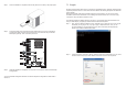
Step 4 Configure the IP address, subnet mask, gateway and DNS. You can consult with the MIS personnel in your company for the related IP address. 2.3.2 RS-232 Connection Port The system can also be managed and configured via the RS-232. In case you have forgotten the IP address you have configured, you can then use RS-232 port to enter the system for configure. The following instructions are based on Windows XP environment. Step 1 Please make connection by using RS-232 cable provided in the Accessory Kit.
Step 4 Configure the related settings. Baud Rate: 115200 Data byte: 8 bite Parity Check: No Stop bits: 1 Flow control: No Step 5 Select the terminal type. Please click File→Properties→Settings. Specify the terminal type as vt100. Then click OK button to complete the connection. Step 6 After the connection, input the username and password and then login. The following operations are similar to the operations via web-based GUI. Please refer to Chapter 3 for instructions.
2.4 LCM architecture reference diagram System Control 2.4.1 LCM (SR5650) [Alarm Mute] [cYes Nod] [Reset] [cYes Nod] [Shutdown] [cYes Nod] [Reset/Shutdown] Use the four function keys, (Up), (Down), ESC (Escape) and ENT (Enter) to control LCM (LCD Control Module). After booting up the system, the following screen will be displayed: xxx.xxx.xxx.
Chapter 3 3.
3.3 Quick Install You can easily create a volume by using the “Quick install” function. On RAID levels 0, 1, 3, 5 and 6, the system will automatically calculate the maximum available capacity, which is subject to the number of your hard disks and currently available capacity. “Quick install” function features a smart program. When the system is installed with 4 or 8 identical hard disks, the system will automatically list all the available RAID levels and the total capacity.
3.4 System Config “System config” function allows you to configure “System name,” “IP address,” “SCSI,” “Login config,” Password,” ”Date,” “Mail,” “SNMP” and “Event log”. 3.4.1 System Name Select “System name” to change system name. The default System name is in accordance with the product name and serial number of the system. For example: S120-000001. 3.4.2 IP Address Select “IP address” to change the IP address for remote control page.
3.4.4 Login Config Select “Login config” to configure the time of single login and auto logout. Single login can prevent multiple users from simultaneously accessing the same data. 1. Auto logout: The options include (1) Disable (2) 5 min (3) 30 min (4) 1 hour. If a user idles after the specified time elapsed, the system will automatically logout to allow other users to login. 3.4.7 E-Mail Click “Mail” to input up to 3 E-mail addresses for receiving the event notification.
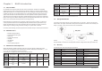
3.4.9 Event Log 3.5.1 Volume Relationship Diagram Click “Event log” to view the event messages. Click “Filter” to select the log type to be displayed. Click “Download” button to save the whole event log as a text file “qlog.txt”. Click “Clear” button to clear the whole event log. Click “Mute” button to stop system alerts. There are three methods to display the event log: “Show events” in the event log page, “Pop up events” in the pop-up window in the web page, and “Show on LCM” (SR5650).
• Physical Disk Field Description: 3.5.3 Volume Group The slot number of the hard disk. The blue button next to the number indicates “More Information” function. Clicking it shows the details of the hard disk. Click “Volume group” to view the status of each volume group. WWN World Wide Name.
3.5.4 • User Data Volume (UDV) UDV Operation Description: Enter the “User data volume” function to view the status of each user data volume ATTACH LUN Attach to a LUN CREATE Create a user data volume DELETE Delete a user data volume 3.5.5 Cache Volume (CV) Enter “Cache volume” function to view the status of cache volume The global cache volume is a default cache volume, which is automatically created after power on, and cannot be deleted. The size of global cache is based on the RAM size.
3.5.6 Logical Unit Number (LUN) Enter “Logical unit” function to view the status of attached logical unit number of each UDV • 1. Select “/ Volume config / Volume group”. 2. Click “ 3. Input a VG Name, then choose a RAID level from the list, click “ ”. ” to choose the RAID PD slot(s), then click “ “ 4. Confirm the results. Click “ ” if all the settings are correct. 5. OK. A VG has been created.
1. 2. 3. 4. Select a UDV Configure the bus ID, SCSI ID and the LUN to be attached to. Then click “ OK Repeat the steps above to create another UDV ” Figure 3.5.7.4 (Figure 3.5.7.4: Creating UDVs named “UDV-R5-1” and “UDV-R5-2”, related to “VG-R5”. The size of “UDV-R5-1” is 50GB and the size of “UDV-R5-2” is 98GB. The status of both UDVs is online, write-back, high priority with 427MB-sized cache memory. The complete percentage of the initialization of “UDV-R51” is 15%. There is no LUN attached.
Step 6 Detach LUN from UDV Enter “/ Volume config / Logical unit” Step 9 Free global spare disk To free global spare disks, please follow the steps below: 1. Select “/ Volume config / Physical disk” 2. Select the global spare disk by ticking the checkbox, then click “ free the disk(s) ” to Step 10 OK, all volumes have been deleted • Example 2 Example 2 is to create two UDVs in one VG. One UDV shares global cache volume while the other uses dedicated cache volume.
Step 2 Create VG (Volume Group) Please refer to Step 1 of Example 1 to create a VG Step 3 Create UDV (User Data Volume) Please refer to Step 2 of Example 1 to create a UDV. To create a UDV with dedicated cache volume, please follow the steps below: Figure 3.5.7.11 (Figure 3.5.7.11: In “/ Volume config / Cache volume”, “UDV-R5-2” uses dedicated cache memory with size 200MB.) Figure 3.5.7.9 1. Select “/ Volume config / User data volume”. 2. Click “ ” 3.
3.6 Enclosure Management “Enclosure management” function allows the administrator to manage the other related information, including “SAF-TE config”, “Hardware Monitor”, “S.M.A.R.T.” and “UPS” functions. To provide enclosure management, the system implements different sensors, such as temperature sensor, voltage sensor, hard disk sensor, fan sensor, power sensor and LED indicators. As these sensors come with different hardware characteristics, each requires different detection time as listed below: 1.
out of tolerance. The advanced notice of possible hard disk failure allows users to back up hard disk or replace the hard disk. This is much better than hard disk crash when it is writing data or rebuilding a failed hard disk. After you enter the “S.M.A.R.T.” function, the S.M.A.R.T. information will be displayed. The number is the current value and the number in parenthesis is the default threshold value. The threshold values are different according to hard disk vendors.
3.7.1 Upgrade 3.7.4 You can enter the “Upgrade” function to upgrade firmware. Please prepare your new firmware file named to select the file. After you click “xxxx.bin”, then click” automatically start and complete the upgrade. Log Import & Export You can click the “Congif import & export” function to import/export the configures , the system will Figure 3.7.1.1 When upgrading, a status window will appear. After upgrading, the system must reboot.
Chapter 4 4.1 Advanced Operation Rebuild In a VG that is set as protected by RAID level (e.g.: RAID 3, RAID 5, or RAID 6), if one physical disk has been failed, unplugged or removed, then, the VG status is changed. The system will search for available space to rebuild the data to ensure data integrity. It will use the dedicated spare disk as rebuild disk first, then the global spare disk. STARDOM SCSI Series Products support the Auto-Rebuild function.
4.3 UDV Expansion To expand UDV size, please follow the steps below. 1. Select “/ Volume config / User data volume” 2. Select the UDV to be expanded and click the “ ” button next to the number in the Size field. 3. Change the volume size. The volume size must be larger than the original value. Then click “ ” to start expansion 4. Expansion starts. If UDV needs initialization, it will display an “I” in “Status 3” field and the complete percentage “R%” Figure 4.2.2 (Figure 4.2.
Chapter 5 5.1 Application Description Storage Capacity Expansion STARDOM SCSI Series Products are equipped with SCSI Ultra 320 dual-channel connection interface, providing 4 SATA expansion interfaces with RAID function plus 4 eSATA expansion interfaces. When connected with 4-bay external storage system (ex.ST7610-4S-S2 or ST5650-4S-S2), your system can be upgraded to a SCSI RAID supporting 8 (4+4) hard disks. It allows user to upgrade the storage capacity at any time when required.
B. Event notifications Info Admin Logout OK Info: Admin logout from via . Error Thermal critical Error: System Overheated!!! The system will do the auto shutdown immediately. Warning Thermal warning Warning: System temperature is a little bit higher. Error Voltage critical Error: System voltages failed!!! The system will do the auto shutdown immediately Warning Voltage warning Warning: System voltage is a little bit higher/lower.
• LVM events Level Type VG Created OK Info: VG has been created. Warning VG Created Fail Warning: Fail to create VG . Info VG Deleted Info: VG has been deleted. Info UDV Created OK Info: UDV has been created. Warning UDV Created Fail Warning: Fail to create UDV . Info UDV Deleted Info: UDV has been deleted. Info UDV Attached OK Info: UDV has been LUN-attached. Warning UDV Attached Fail Warning: Fail to attach LUN to UDV .
C. Using Notices 1. In Microsoft Windows server 2003 or Windows XP, at least one LUN 0 must be configured for each SCSI ID. Otherwise the volume cannot be identified. Windows 2000 server doesn’t have this limitation. A: In Microsoft Windows server 2003 or Windows XP, add the LUN from LUN 0. 2. In Linux environment, there will be some problems in using Adapter SCSI Card 29320A-R and 39320A-R and the transfer rate cannot reach the Ultra 320 standard.