
Full Product Manual
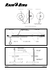

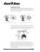
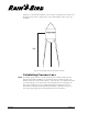
Table Of Contents
- Low-Volume Landscape Irrigation Design Manual
- FOREWORD
- CONTENTS
- 1 WHAT IS XERIGATION®?
- 2 THE DESIGN PROCESS
- 3 GATHER SITE DATA
- LOW-VOLUME DESIGN WORKSHEET: DENSE HYDROZONE
- Calculating Water Requirements
- BASE PLANTS IN DENSE HYDROZONES
- TABLE 3-1: MINIMUM FILTRATION REQUIREMENTS
- TABLE 3-2: DETERMINING THE SOIL TYPE
- TABLE 3-3: SOIL INFILTRATION AND WETTING PATTERN
- TABLE 3-4: PET RATES BASED ON CLIMATE
- Hydrozones
- Chapter 3 Review
- Figure 3-3: Sample Plot Plan—Doyle Residence
- Figure 3-4: Sample Site Data Worksheet—Doyle Residence
- Answer Key
- 4 DETERMINE PLANT WATER REQUIREMENTS
- Figure 4-1: Dense Hydrozone Design Worksheet
- Calculating Water Requirements
- TABLE 4-1: BASE PLANTS IN DENSE HYDROZONES
- Calculate K c
- TABLE 4-2: ESTIMATED SPECIES FACTORS
- TABLE 4-3: ESTIMATED DENSITY FACTORS
- TABLE 4-4: ESTIMATED MICROCLIMATE FACTORS
- Calculate Water Require-ment for Dense Plantings
- Calculate Water Requirement for Individual Plants in a Sparse Hydrozone
- Area of Plant Canopy
- Application Efficiency
- Water Requirement (GPD)
- Chapter 4 Review
- Answer Key
- 5 IRRIGATE BASE PLANTS
- Identifying the Base Plant
- Emission Devices
- Labor Cost Considerations
- TABLE 5-1: XERIGATION EMISSION DEVICE APPLICATION MATRIX
- Dense Plantings
- TABLE 5-2: LANDSCAPE DRIPLINE CHOICES
- TABLE 5-3: LANDSCAPE DRIPLINE SPACINGS AND FLOW RATES
- LATERAL LINE SPACING WORKSHEET
- Figure 5-3: Equal Lateral Line Spacing
- Landscape Dripline: A More Technical Approach
- TABLE 5-4: MINIMUM RECOMMENDED WATERING DEPTHS
- Emitter Spacing Versus Watering Depth
- TABLE 5-5: MAXIMUM EMISSION DEVICE SPACING (INCHES)
- TABLE 5-6: RECOMMENDED EMITTER SPACING
- Xeri-Sprays™
- Sparse Plantings
- Selecting Emitters
- TABLE 5-7: EMISSION DEVICE SELECTION
- Recommended Emitter Placement
- Calculating the Wetted Area
- TABLE 5-8: AREA WETTED BY EACH EMITTER (SQ. FT.)
- Chapter Review
- Answer Key
- 6 CALCULATE SYSTEM RUN TIME
- Calculate System Run Time
- Dense Plantings
- TABLE 6-1: EMITTER DISCHARGE RATES (EDR) FOR LANDSCAPE DRIPLINE IN INCHES PER HOUR*
- Sparse Planting
- 2.Determine Maximum Run Time
- TABLE 6-2: MAXIMUM SYSTEM RUN TIMES FOR COARSE SOIL
- TABLE 6-3: MAXIMUM SYSTEM RUN TIME FOR MEDIUM SOIL
- TABLE 6-4: MAXIMUM SYSTEM RUN TIME FOR FINE SOIL
- 3.Determine Irrigation Interval
- Chapter Review
- Answer Key
- 7 IRRIGATE NON-BASE PLANTS
- 8 SYSTEM LAYOUT
- Figure 8-1: Correct placement of emitters
- Figure 8-2: Emitter layout options
- Figure 8-3: Layout using poly drip tubing (Xeri-Tube 700)
- Figure 8-4: Layout using rigid PVC
- Using Inline Tubing
- Placing Supplemental Emitters
- Figure 8-5: Placement of supplemental emitters for shrubs or trees: top view
- Figure 8-6: Placement of supplemental emitters for shrubs or trees: section view
- System Configuration
- TABLE 8-1: SPACING OF STAKES AND STAPLES
- Figure 8-7: Landscape Dripline system configuration
- Irrigating Slopes
- Figure 8-8: Correct emitter placement on slope
- Figure 8-9: Correct placement of lateral pipe on slope
- Figure 8-10: Placement of Landscape Dripline on a slope
- Container Plants
- Figure 8-11: Micro-bubbler in a container plant
- Figure 8-12: Multiple emitters in a container plant
- Figure 8-13: Xeri-Bug emitter in a hanging basket
- 9 SYSTEM HYDRAULICS
- Water Pressure
- Figure 9-1: Determining static pressure based on elevation
- Calculating Pressure Loss
- Figure 9-2: Total flow worksheet
- Figure 9-3: Completed total flow worksheet
- Figure 9-4: Flow rate worksheet
- TABLE 9-1: MAXIMUM FLOW RATES
- Determine Maximum Lateral Lengths
- TABLE 9-2: MAXIMUM LATERAL LENGTHS
- TABLE 9-3: MAXIMUM LATERAL LENGTH XT-700
- Pressure Loss Calculation
- TABLE 9-4: MINIMUM/MAXIMUM FLOWS FOR PROPER VALVE PERFORMANCE
- TABLE 9-5: MINIMUM FLOW REQUIREMENT FOR PROPER VALVE PERFORMANCE*
- TABLE 9-6: FRICTION LOSS CHARACTERISTICS OF XERI-TUBE 700
- High Pressure
- Maximum Inlet Pressure
- TABLE 9-7: RAIN BIRD PRESSURE REGULATORS
- Hydraulics Worksheet
- 10 INSTALLATION, MAINTENANCE AND TROUBLESHOOTING
- A FORMULAS FOR XERIGATION DESIGN
- B PET DATA
- C FRICTION LOSS AND PERFORMANCE DATA
- D XERIGATION PLANNING FORMS
- E GLOSSARY
- F XERIGATION PRODUCT LINE
- INSTALLATION DETAILS
- BIBLIOGRAPHY
- INDEX
- Contact Information

In Figure 9-1, the distance from the water’s surface to ground level is 160 feet. To
find the static pressure at ground level, you would multiply .433 by 160 to get
69.28 PSI.
160’
Figure 9-1: Determining static pressure based on elevation
Flow
Calculating Pressure Loss
To calculate pressure losses, you need to know the total flow required by the
hydrozone (in GPH or GPM). As a general rule for low-volume systems, you
should design the system so that you have a pressure of at least 30 PSI at the inlet
to each lateral pipe. As a conservative rule of thumb, flow rates through each
lateral pipe should not exceed 4.7 GPM (282 GPH). In addition, for ease of
maintenance and hydraulic functionality, individual, continuous runs of 1/2"
lateral poly drip tubing in one direction should not exceed 500 feet.
Page 64 Chapter 9
®