
Full Product Manual
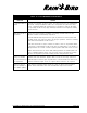
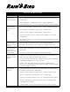
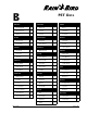
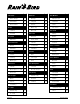

Table Of Contents
- Low-Volume Landscape Irrigation Design Manual
- FOREWORD
- CONTENTS
- 1 WHAT IS XERIGATION®?
- 2 THE DESIGN PROCESS
- 3 GATHER SITE DATA
- LOW-VOLUME DESIGN WORKSHEET: DENSE HYDROZONE
- Calculating Water Requirements
- BASE PLANTS IN DENSE HYDROZONES
- TABLE 3-1: MINIMUM FILTRATION REQUIREMENTS
- TABLE 3-2: DETERMINING THE SOIL TYPE
- TABLE 3-3: SOIL INFILTRATION AND WETTING PATTERN
- TABLE 3-4: PET RATES BASED ON CLIMATE
- Hydrozones
- Chapter 3 Review
- Figure 3-3: Sample Plot Plan—Doyle Residence
- Figure 3-4: Sample Site Data Worksheet—Doyle Residence
- Answer Key
- 4 DETERMINE PLANT WATER REQUIREMENTS
- Figure 4-1: Dense Hydrozone Design Worksheet
- Calculating Water Requirements
- TABLE 4-1: BASE PLANTS IN DENSE HYDROZONES
- Calculate K c
- TABLE 4-2: ESTIMATED SPECIES FACTORS
- TABLE 4-3: ESTIMATED DENSITY FACTORS
- TABLE 4-4: ESTIMATED MICROCLIMATE FACTORS
- Calculate Water Require-ment for Dense Plantings
- Calculate Water Requirement for Individual Plants in a Sparse Hydrozone
- Area of Plant Canopy
- Application Efficiency
- Water Requirement (GPD)
- Chapter 4 Review
- Answer Key
- 5 IRRIGATE BASE PLANTS
- Identifying the Base Plant
- Emission Devices
- Labor Cost Considerations
- TABLE 5-1: XERIGATION EMISSION DEVICE APPLICATION MATRIX
- Dense Plantings
- TABLE 5-2: LANDSCAPE DRIPLINE CHOICES
- TABLE 5-3: LANDSCAPE DRIPLINE SPACINGS AND FLOW RATES
- LATERAL LINE SPACING WORKSHEET
- Figure 5-3: Equal Lateral Line Spacing
- Landscape Dripline: A More Technical Approach
- TABLE 5-4: MINIMUM RECOMMENDED WATERING DEPTHS
- Emitter Spacing Versus Watering Depth
- TABLE 5-5: MAXIMUM EMISSION DEVICE SPACING (INCHES)
- TABLE 5-6: RECOMMENDED EMITTER SPACING
- Xeri-Sprays™
- Sparse Plantings
- Selecting Emitters
- TABLE 5-7: EMISSION DEVICE SELECTION
- Recommended Emitter Placement
- Calculating the Wetted Area
- TABLE 5-8: AREA WETTED BY EACH EMITTER (SQ. FT.)
- Chapter Review
- Answer Key
- 6 CALCULATE SYSTEM RUN TIME
- Calculate System Run Time
- Dense Plantings
- TABLE 6-1: EMITTER DISCHARGE RATES (EDR) FOR LANDSCAPE DRIPLINE IN INCHES PER HOUR*
- Sparse Planting
- 2.Determine Maximum Run Time
- TABLE 6-2: MAXIMUM SYSTEM RUN TIMES FOR COARSE SOIL
- TABLE 6-3: MAXIMUM SYSTEM RUN TIME FOR MEDIUM SOIL
- TABLE 6-4: MAXIMUM SYSTEM RUN TIME FOR FINE SOIL
- 3.Determine Irrigation Interval
- Chapter Review
- Answer Key
- 7 IRRIGATE NON-BASE PLANTS
- 8 SYSTEM LAYOUT
- Figure 8-1: Correct placement of emitters
- Figure 8-2: Emitter layout options
- Figure 8-3: Layout using poly drip tubing (Xeri-Tube 700)
- Figure 8-4: Layout using rigid PVC
- Using Inline Tubing
- Placing Supplemental Emitters
- Figure 8-5: Placement of supplemental emitters for shrubs or trees: top view
- Figure 8-6: Placement of supplemental emitters for shrubs or trees: section view
- System Configuration
- TABLE 8-1: SPACING OF STAKES AND STAPLES
- Figure 8-7: Landscape Dripline system configuration
- Irrigating Slopes
- Figure 8-8: Correct emitter placement on slope
- Figure 8-9: Correct placement of lateral pipe on slope
- Figure 8-10: Placement of Landscape Dripline on a slope
- Container Plants
- Figure 8-11: Micro-bubbler in a container plant
- Figure 8-12: Multiple emitters in a container plant
- Figure 8-13: Xeri-Bug emitter in a hanging basket
- 9 SYSTEM HYDRAULICS
- Water Pressure
- Figure 9-1: Determining static pressure based on elevation
- Calculating Pressure Loss
- Figure 9-2: Total flow worksheet
- Figure 9-3: Completed total flow worksheet
- Figure 9-4: Flow rate worksheet
- TABLE 9-1: MAXIMUM FLOW RATES
- Determine Maximum Lateral Lengths
- TABLE 9-2: MAXIMUM LATERAL LENGTHS
- TABLE 9-3: MAXIMUM LATERAL LENGTH XT-700
- Pressure Loss Calculation
- TABLE 9-4: MINIMUM/MAXIMUM FLOWS FOR PROPER VALVE PERFORMANCE
- TABLE 9-5: MINIMUM FLOW REQUIREMENT FOR PROPER VALVE PERFORMANCE*
- TABLE 9-6: FRICTION LOSS CHARACTERISTICS OF XERI-TUBE 700
- High Pressure
- Maximum Inlet Pressure
- TABLE 9-7: RAIN BIRD PRESSURE REGULATORS
- Hydraulics Worksheet
- 10 INSTALLATION, MAINTENANCE AND TROUBLESHOOTING
- A FORMULAS FOR XERIGATION DESIGN
- B PET DATA
- C FRICTION LOSS AND PERFORMANCE DATA
- D XERIGATION PLANNING FORMS
- E GLOSSARY
- F XERIGATION PRODUCT LINE
- INSTALLATION DETAILS
- BIBLIOGRAPHY
- INDEX
- Contact Information

Installation, Maintenance and Troubleshooting Page 75
TABLE 10-1: RECOMMENDED MAINTENANCE
Interval Action
Design/Installation
phase
Consider accessibility of valves, filters, and emission devices to maintenance
personnel. During installation, make sure components are placed for easy
access. Completely flush the system prior to operation to remove all debris.
Be especially careful to keep pipe shavings and burrs from rigid PVC tubing
out of the lines.
After two weeks of
operation
Inspect and clean all filters. Establish a cleaning schedule based on the
amount of debris found during inspection.
Perform walk-through inspection for signs of plant stress. Run system and
carefully check each emission device for proper operation. Listen for running
water that could indicate breaks in lines.
Flush lines and look for signs of debris in water. Debris or suspended matter
in the water could indicate breaks in the lines or failed filters. If no breaks or
damaged filters are found, consider replacing filters with finer mesh screens.
Adjust emission devices to assure that wetting patterns are within plant root
zones. If wetting pattern can be seen on top of soil, be sure that it overlaps
the base of the plant to provide leaching of salts away from the plant.
Every 1-2 months
or as needed based
on experience
Examine and clean all filters. Replace filter screens if necessary. Perform a
walk-through to look for signs of plant stress. Check all emission devices for
location and flow. Adjust, clean, or replace emission devices as required.
Twice per year or
more frequently if
poor water quality
Flush all lines. Examine water sample for signs of debris and suspended
matter. Flush until water runs clear (should take only a few seconds).
®