
Full Product Manual


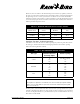
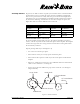
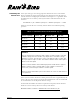
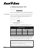
Table Of Contents
- Low-Volume Landscape Irrigation Design Manual
- FOREWORD
- CONTENTS
- 1 WHAT IS XERIGATION®?
- 2 THE DESIGN PROCESS
- 3 GATHER SITE DATA
- LOW-VOLUME DESIGN WORKSHEET: DENSE HYDROZONE
- Calculating Water Requirements
- BASE PLANTS IN DENSE HYDROZONES
- TABLE 3-1: MINIMUM FILTRATION REQUIREMENTS
- TABLE 3-2: DETERMINING THE SOIL TYPE
- TABLE 3-3: SOIL INFILTRATION AND WETTING PATTERN
- TABLE 3-4: PET RATES BASED ON CLIMATE
- Hydrozones
- Chapter 3 Review
- Figure 3-3: Sample Plot Plan—Doyle Residence
- Figure 3-4: Sample Site Data Worksheet—Doyle Residence
- Answer Key
- 4 DETERMINE PLANT WATER REQUIREMENTS
- Figure 4-1: Dense Hydrozone Design Worksheet
- Calculating Water Requirements
- TABLE 4-1: BASE PLANTS IN DENSE HYDROZONES
- Calculate K c
- TABLE 4-2: ESTIMATED SPECIES FACTORS
- TABLE 4-3: ESTIMATED DENSITY FACTORS
- TABLE 4-4: ESTIMATED MICROCLIMATE FACTORS
- Calculate Water Require-ment for Dense Plantings
- Calculate Water Requirement for Individual Plants in a Sparse Hydrozone
- Area of Plant Canopy
- Application Efficiency
- Water Requirement (GPD)
- Chapter 4 Review
- Answer Key
- 5 IRRIGATE BASE PLANTS
- Identifying the Base Plant
- Emission Devices
- Labor Cost Considerations
- TABLE 5-1: XERIGATION EMISSION DEVICE APPLICATION MATRIX
- Dense Plantings
- TABLE 5-2: LANDSCAPE DRIPLINE CHOICES
- TABLE 5-3: LANDSCAPE DRIPLINE SPACINGS AND FLOW RATES
- LATERAL LINE SPACING WORKSHEET
- Figure 5-3: Equal Lateral Line Spacing
- Landscape Dripline: A More Technical Approach
- TABLE 5-4: MINIMUM RECOMMENDED WATERING DEPTHS
- Emitter Spacing Versus Watering Depth
- TABLE 5-5: MAXIMUM EMISSION DEVICE SPACING (INCHES)
- TABLE 5-6: RECOMMENDED EMITTER SPACING
- Xeri-Sprays™
- Sparse Plantings
- Selecting Emitters
- TABLE 5-7: EMISSION DEVICE SELECTION
- Recommended Emitter Placement
- Calculating the Wetted Area
- TABLE 5-8: AREA WETTED BY EACH EMITTER (SQ. FT.)
- Chapter Review
- Answer Key
- 6 CALCULATE SYSTEM RUN TIME
- Calculate System Run Time
- Dense Plantings
- TABLE 6-1: EMITTER DISCHARGE RATES (EDR) FOR LANDSCAPE DRIPLINE IN INCHES PER HOUR*
- Sparse Planting
- 2.Determine Maximum Run Time
- TABLE 6-2: MAXIMUM SYSTEM RUN TIMES FOR COARSE SOIL
- TABLE 6-3: MAXIMUM SYSTEM RUN TIME FOR MEDIUM SOIL
- TABLE 6-4: MAXIMUM SYSTEM RUN TIME FOR FINE SOIL
- 3.Determine Irrigation Interval
- Chapter Review
- Answer Key
- 7 IRRIGATE NON-BASE PLANTS
- 8 SYSTEM LAYOUT
- Figure 8-1: Correct placement of emitters
- Figure 8-2: Emitter layout options
- Figure 8-3: Layout using poly drip tubing (Xeri-Tube 700)
- Figure 8-4: Layout using rigid PVC
- Using Inline Tubing
- Placing Supplemental Emitters
- Figure 8-5: Placement of supplemental emitters for shrubs or trees: top view
- Figure 8-6: Placement of supplemental emitters for shrubs or trees: section view
- System Configuration
- TABLE 8-1: SPACING OF STAKES AND STAPLES
- Figure 8-7: Landscape Dripline system configuration
- Irrigating Slopes
- Figure 8-8: Correct emitter placement on slope
- Figure 8-9: Correct placement of lateral pipe on slope
- Figure 8-10: Placement of Landscape Dripline on a slope
- Container Plants
- Figure 8-11: Micro-bubbler in a container plant
- Figure 8-12: Multiple emitters in a container plant
- Figure 8-13: Xeri-Bug emitter in a hanging basket
- 9 SYSTEM HYDRAULICS
- Water Pressure
- Figure 9-1: Determining static pressure based on elevation
- Calculating Pressure Loss
- Figure 9-2: Total flow worksheet
- Figure 9-3: Completed total flow worksheet
- Figure 9-4: Flow rate worksheet
- TABLE 9-1: MAXIMUM FLOW RATES
- Determine Maximum Lateral Lengths
- TABLE 9-2: MAXIMUM LATERAL LENGTHS
- TABLE 9-3: MAXIMUM LATERAL LENGTH XT-700
- Pressure Loss Calculation
- TABLE 9-4: MINIMUM/MAXIMUM FLOWS FOR PROPER VALVE PERFORMANCE
- TABLE 9-5: MINIMUM FLOW REQUIREMENT FOR PROPER VALVE PERFORMANCE*
- TABLE 9-6: FRICTION LOSS CHARACTERISTICS OF XERI-TUBE 700
- High Pressure
- Maximum Inlet Pressure
- TABLE 9-7: RAIN BIRD PRESSURE REGULATORS
- Hydraulics Worksheet
- 10 INSTALLATION, MAINTENANCE AND TROUBLESHOOTING
- A FORMULAS FOR XERIGATION DESIGN
- B PET DATA
- C FRICTION LOSS AND PERFORMANCE DATA
- D XERIGATION PLANNING FORMS
- E GLOSSARY
- F XERIGATION PRODUCT LINE
- INSTALLATION DETAILS
- BIBLIOGRAPHY
- INDEX
- Contact Information

Irrigate Base Plants Page 37
However, there is a limit to the horizontal spread of water by capillary action in
the soil even when that soil has been well amended and is consistent throughout
the planting area. As a result, you must be careful not to exceed the maximum
allowable spacing of the emitters as shown in Table 5-5. If this maximum spacing
is exceeded, dry spots between emitters will result and it is likely that salts will
build up around the plants’ roots.
Applying The More Technical Approach
Use Table 5-6 to select the correct emitter spacing for your base plant. First locate
the soil type, and then the desired watering depth. Select the emitter spacing
indicated in the right hand column.
EXAMPLE
To irrigate to a depth of 9” in medium soil, choose Landscape Dripline tubing
with 0.9 or 0.6 GPH emitters spaced at 18” intervals and lateral spacing that
does not exceed 18”.
In many cases, you can choose the flow rate based on your preference for system
run time; the higher the flow rate, the less time it takes to deliver a given amount
of water to the plant. However, you should always use 0.6 GPH emitters for very
fine soils to avoid runoff.
TABLE 5-5: MAXIMUM EMISSION DEVICE SPACING (INCHES)
Emitter Flow Coarse Medium Fine
0.6 GPH 12.0 27.6 39.9
0.9 GPH 20.4 33.7 42.9
2.0 GPH 39.6 51.6 67.2
TABLE 5-6: RECOMMENDED EMITTER SPACING
Soil Type Minimum Desired
Watering Depth
Emitter Spacing
Coarse
6"
12"
18"
Use Micro-Sprays
12"
18"
Medium
6"
9"
12"
18"
12"
18"
24"
36"
Fine
6"
9"
12"
24"
36"
48"
®