
Full Product Manual
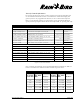
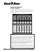
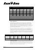
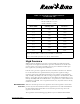
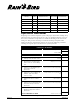
Table Of Contents
- Low-Volume Landscape Irrigation Design Manual
- FOREWORD
- CONTENTS
- 1 WHAT IS XERIGATION®?
- 2 THE DESIGN PROCESS
- 3 GATHER SITE DATA
- LOW-VOLUME DESIGN WORKSHEET: DENSE HYDROZONE
- Calculating Water Requirements
- BASE PLANTS IN DENSE HYDROZONES
- TABLE 3-1: MINIMUM FILTRATION REQUIREMENTS
- TABLE 3-2: DETERMINING THE SOIL TYPE
- TABLE 3-3: SOIL INFILTRATION AND WETTING PATTERN
- TABLE 3-4: PET RATES BASED ON CLIMATE
- Hydrozones
- Chapter 3 Review
- Figure 3-3: Sample Plot Plan—Doyle Residence
- Figure 3-4: Sample Site Data Worksheet—Doyle Residence
- Answer Key
- 4 DETERMINE PLANT WATER REQUIREMENTS
- Figure 4-1: Dense Hydrozone Design Worksheet
- Calculating Water Requirements
- TABLE 4-1: BASE PLANTS IN DENSE HYDROZONES
- Calculate K c
- TABLE 4-2: ESTIMATED SPECIES FACTORS
- TABLE 4-3: ESTIMATED DENSITY FACTORS
- TABLE 4-4: ESTIMATED MICROCLIMATE FACTORS
- Calculate Water Require-ment for Dense Plantings
- Calculate Water Requirement for Individual Plants in a Sparse Hydrozone
- Area of Plant Canopy
- Application Efficiency
- Water Requirement (GPD)
- Chapter 4 Review
- Answer Key
- 5 IRRIGATE BASE PLANTS
- Identifying the Base Plant
- Emission Devices
- Labor Cost Considerations
- TABLE 5-1: XERIGATION EMISSION DEVICE APPLICATION MATRIX
- Dense Plantings
- TABLE 5-2: LANDSCAPE DRIPLINE CHOICES
- TABLE 5-3: LANDSCAPE DRIPLINE SPACINGS AND FLOW RATES
- LATERAL LINE SPACING WORKSHEET
- Figure 5-3: Equal Lateral Line Spacing
- Landscape Dripline: A More Technical Approach
- TABLE 5-4: MINIMUM RECOMMENDED WATERING DEPTHS
- Emitter Spacing Versus Watering Depth
- TABLE 5-5: MAXIMUM EMISSION DEVICE SPACING (INCHES)
- TABLE 5-6: RECOMMENDED EMITTER SPACING
- Xeri-Sprays™
- Sparse Plantings
- Selecting Emitters
- TABLE 5-7: EMISSION DEVICE SELECTION
- Recommended Emitter Placement
- Calculating the Wetted Area
- TABLE 5-8: AREA WETTED BY EACH EMITTER (SQ. FT.)
- Chapter Review
- Answer Key
- 6 CALCULATE SYSTEM RUN TIME
- Calculate System Run Time
- Dense Plantings
- TABLE 6-1: EMITTER DISCHARGE RATES (EDR) FOR LANDSCAPE DRIPLINE IN INCHES PER HOUR*
- Sparse Planting
- 2.Determine Maximum Run Time
- TABLE 6-2: MAXIMUM SYSTEM RUN TIMES FOR COARSE SOIL
- TABLE 6-3: MAXIMUM SYSTEM RUN TIME FOR MEDIUM SOIL
- TABLE 6-4: MAXIMUM SYSTEM RUN TIME FOR FINE SOIL
- 3.Determine Irrigation Interval
- Chapter Review
- Answer Key
- 7 IRRIGATE NON-BASE PLANTS
- 8 SYSTEM LAYOUT
- Figure 8-1: Correct placement of emitters
- Figure 8-2: Emitter layout options
- Figure 8-3: Layout using poly drip tubing (Xeri-Tube 700)
- Figure 8-4: Layout using rigid PVC
- Using Inline Tubing
- Placing Supplemental Emitters
- Figure 8-5: Placement of supplemental emitters for shrubs or trees: top view
- Figure 8-6: Placement of supplemental emitters for shrubs or trees: section view
- System Configuration
- TABLE 8-1: SPACING OF STAKES AND STAPLES
- Figure 8-7: Landscape Dripline system configuration
- Irrigating Slopes
- Figure 8-8: Correct emitter placement on slope
- Figure 8-9: Correct placement of lateral pipe on slope
- Figure 8-10: Placement of Landscape Dripline on a slope
- Container Plants
- Figure 8-11: Micro-bubbler in a container plant
- Figure 8-12: Multiple emitters in a container plant
- Figure 8-13: Xeri-Bug emitter in a hanging basket
- 9 SYSTEM HYDRAULICS
- Water Pressure
- Figure 9-1: Determining static pressure based on elevation
- Calculating Pressure Loss
- Figure 9-2: Total flow worksheet
- Figure 9-3: Completed total flow worksheet
- Figure 9-4: Flow rate worksheet
- TABLE 9-1: MAXIMUM FLOW RATES
- Determine Maximum Lateral Lengths
- TABLE 9-2: MAXIMUM LATERAL LENGTHS
- TABLE 9-3: MAXIMUM LATERAL LENGTH XT-700
- Pressure Loss Calculation
- TABLE 9-4: MINIMUM/MAXIMUM FLOWS FOR PROPER VALVE PERFORMANCE
- TABLE 9-5: MINIMUM FLOW REQUIREMENT FOR PROPER VALVE PERFORMANCE*
- TABLE 9-6: FRICTION LOSS CHARACTERISTICS OF XERI-TUBE 700
- High Pressure
- Maximum Inlet Pressure
- TABLE 9-7: RAIN BIRD PRESSURE REGULATORS
- Hydraulics Worksheet
- 10 INSTALLATION, MAINTENANCE AND TROUBLESHOOTING
- A FORMULAS FOR XERIGATION DESIGN
- B PET DATA
- C FRICTION LOSS AND PERFORMANCE DATA
- D XERIGATION PLANNING FORMS
- E GLOSSARY
- F XERIGATION PRODUCT LINE
- INSTALLATION DETAILS
- BIBLIOGRAPHY
- INDEX
- Contact Information

TABLE 9-5: MINIMUM FLOW REQUIREMENT FOR PROPER VALVE PERFORMANCE*
Valve Series
DV
(3/4", 1")
ASVF
(3/4", 1")
PGA (1") PEB (1") GB (1") EFB-CP (1")
Minimum Flow 3 GPM 3 GPM 2 GPM 0.25 GPM 5 GPM 5 GPM
* Assumes no filtration is provided upstream of the valve as described in Table 9-4.
Page 70 Chapter 9
Flow Compatibility
It is important to note that all electric control valves have a minimum flow
specification that can be found in the valve manufacturer’s catalog. For Rain
Bird, these minimum flow rates are listed in Table 9-5. If the flow in a drip
hydrozone falls below the valve’s minimum flow specification and this goes
unchecked, trouble can occur. Water weepage from the valve or a valve that just
won’t shut off electrically are two of the more common problems that occur,
especially in drip retrofit situations.
One way to avoid this low flow valve problem is to use one of Rain Bird’s
Xerigation Control Zones. These control zones put a 200-mesh filter immediately
upstream of the electric control valve and thereby deliver a minimum flow
specification of 0.2 GPM or 12 GPH. The drip filter is pressure-rated to 150 PSI so
it performs reliably upstream of the valve, under constant pressure. Rain Bird
also offers the 100-PEB valve, which has a very low minimum flow specification
of 0.25 GPM.
*
Lateral Pipe/Tubing
In low-volume systems, 1/2" distribution tubing is typically used for lateral
piping. You calculate the pressure loss in this tubing in the same way you do for
PVC pipe. Table 9-6 provides friction loss characteristics for XT-700, Rain Bird’s
thick-walled, heavy-duty 1/2" polyethylene tubing.
TABLE 9-4: MINIMUM/MAXIMUM FLOWS FOR PROPER VALVE PERFORMANCE
Flow GPM GPH
XACZ-075
PSI
XCZ-075
PSI
75-DVX
PSI
XCZ-100
PSI
100-PEB
PSI
1 60 5.1 3.5 2.5 1.0
3.0
3 180 5.1 3.5 2.5 1.0
2.6
5 300 5.4 3.6 2.9 1.2
2.0
10* 600 9.9 7.5 3.8 5.1
1.5
15* 900 15.9 12.7 4.2 8.8
2.0
20* 1200 24.2 20.2 5.1 14.3
2.5
XCZ-075 pressure loss data above 5 GPM is with PSI-M30X pressure regulator.
Maximum flow rate with "M" style regulators is 22 GPM.
* For flows below 3 GPM, always use RBY Series 200 mesh filter installed upstream of valve.
** For flows greater than 5 GPM, substitute PSI-L30X with a PSI-M30X pressure regulator.
*** Minimum flow rate of 100-PEB valve is 0.25 GPM without the use of an upstream filter
®