MAXI® Remote Location Kit MRLK 900 Installation Instructions
Introduction The MAXI® Remote Location Kit 900 utilizes 900 MHz radios to position a MIM 2-Wire, MIM LINK or MDI at a remote location from the central computer. The MRLK 900 includes two surge protectors to provide in-line protection against lightning at the locations of both radios. These installation instructions assume that the user is already familiar with the installation instructions and physical layout of the MIM 2-Wire, MIM LINK, or MDI products.
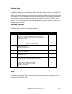
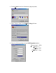
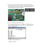
To MIM Antenna Prior to Installation 5 4 6 6 To MIM Antenna 1 1 MASTER SLAVE 4 3A AC POWER 4 2 3B 2 After MRLK 900 Installation FIGURE 1 AC POWER Existing cable and connector
Radio Configuration Prior to the installation of the MRLK 900, the FreeWave 900 MHz Spread Spectrum radios require configuration. All adjustments are done through the FreeWave setup program, a user interface which eliminates the need for setup diskettes, DIP switch settings, or custom software. The setup program is invoked by connecting the FreeWave radio to any terminal program, setting the computer baud rate to 19,200, and putting the radio into setup mode.
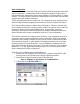
4. Enter a Name for the New Connection (temporary name). 5. Select “Direct to Com1” from Connect Using pull-down. 6.
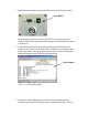
7. Invoke the setup program by pressing the black button on the back of the radio: Setup Button When the setup program is invoked, all three LEDs on the front panel of the FreeWave radio will turn green and will remain green for the entire time the radio is in setup mode. 8. Verify that the serial number on the setup program screen matches the serial number on the bottom of the FreeWave radio.
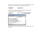
be verified by checking the second line of text in the SET MODEM MODE menu as shown below. The second line of text should show the following: For Master radio: For Slave radio: Modem Mode is 0 Modem Mode is 1 If the radios have not been pre-configured correctly for the Modem Mode, then configure each radio using the following: For Master radio: For Slave radio: Enter “0” to select Point to Point Master. Enter “1” to select Point to Point Slave.
10. Verify that each radio has been pre-configured to communicate with the other by checking the entries in the Call Book for each radio. Enter “2” to Edit Call Book from the Main Menu. For Master radio: The Number for Entry (0) should match the serial number found on the bottom of the Slave radio. For Slave radio: The Number for Entry (0) should match the serial number found on the bottom of the Master radio.
11. Determine the baud rate setting for the MIM by looking at the baud rate select jumper on the inside of the door as shown below. Use the table below to determine the selected baud rate of the MIM. The baud rate setting for an MDI application can be determined from the existing configuration. Jumper Baud Rate E5 – E4 9,600 E4 – E3 1,200 12. Enter “1” to Set Baud Rate from the Main Menu.
13. After completing the setup program for one of the radios, perform steps 7-13 for the other radio, making sure that the Operation Mode selection is set to the opposite mode of the other radio. After configuring both radios, exit from the HyperTerminal program by closing the window or using the Exit selection in the File dropdown menu. Select Yes to disconnect from the current session of HyperTerminal.