
Use and Care Manual

1
1
SST User Manual
Installation
Tools and Supplies Needed
•
Phillips screwdriver
•
Wire stripper
•
Hammer
•
Valve wire: direct burial, color coded multi-strand (not
included)
•
18 gauge for runs less than 800 feet.
•
14 gauge for runs greater than 800 feet.
•
Watertight splice connectors (not included)
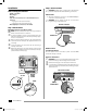
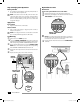
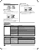
Step 1. Mount Timer
Mount the SST in an accessible location
NOTE: SST indoor timers are for indoor use only. SST outdoor
timers can be used indoors or outdoors.
A
For indoor installation, choose a location within 5 feet of an
AC power outlet and at least 15 feet away from major appli-
ances or air conditioners.
B
Drive a screw into the wall, leaving an 1/8" gap between the
screw-head and the wall (use the supplied wall anchors if
necessary).
C
Locate the keyhole slot on back of the unit and hang it
securely on the screw.
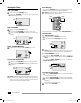
D
Remove the wiring bay cover at the bottom of the unit and
drive a screw through the center hole as shown (use the sup-
plied wall anchors if necessary).
1/8" GAP
SCREW
INDOOR
MODEL
SHOWN
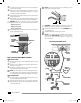
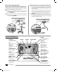
Step 2. Connect Power
c
WARNING: DO NOT plug in or apply power to the timer until
you have completed and checked all wiring connections.
Indoor Timer
Attach the transformer connector to the 24VAC POWER pin
connection on the terminal strip.
c
WARNING: Do not attempt to link two or more timers
together using a single transformer.
SST Indoor Model
TRANSFORMER
CONNECTOR
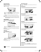
Outdoor Timer
Standard Installation
The SST outdoor version comes with a power cord and 24VAC
transformer already connected.
Hard-wire Installation
c
WARNING: Disconnect or shut o the external power source
before connecting or disconnecting wires to the timer.
A
Remove the wiring bay cover at the bottom of the unit.
B
Locate the wiring compartment in the lower left-hand corner
of the unit and using a screwdriver, unscrew wiring compart-
ment front cover.
SST Outdoor Model
WIRING
COMPARTMENT
SST user manual (EN) web.indd 1 10/11/2016 8:17:23 PM