
Operation Manual


Outdoor Model
WARNING: Electric shock can cause severe injury or
death. Make sure power supply is turned OFF before
connecting power wires.
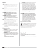
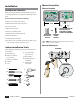
Power Wiring Connections
120VAC (USA) 230VAC (International)
Black supply wire (hot) to the
black transformer wire
Black supply wire (hot) to the black transformer
wire
White supply wire (neutral) to
the white transformer wire
Blue supply wire (neutral) to the blue
transformer wire
Green supply wire (ground)
to the green transformer wire
Green-with-yellow-stripe supply wire (ground)
to the green-with-yellow-stripe transformer
wire (
)
1 2 3 4
VT = VALVE TEST
VT MV COM
24 VAC
GND
SENS
VT MV COM 5 6 7 11 12 13 17 18 19
1 2 3 4 8 9 10 14 15 16 20 21 22
CONNECT
120 VAC
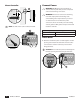
1.
1 2 3 4
VT = VAL VE TEST
VT MV CO M
24 VA C
GN D
SEN S
VT MV COM 5 6 7 11 12 13 17 18 19
1 2 3 4 8 9 1 0 14 15 16 20 21 22
2.
For 120V:
1 2 3 4
VT = VALVE TEST
VT MV COM
24 VAC
GND
SENS
VT MV COM 5 6 7 11 12 13 17 18 19
1 2 3 4 8 9 10 14 15 16 20 21 22
3.
For 230V only:
L
N
3.
NOTE: Use either the provided wire nuts or the
installed connector for this step.
WARNING: Ground wire must be connected to
provide electrical surge protection. Permanently
mounted conduit shall be used for connecting main
voltage to the controller.
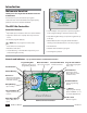
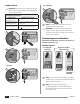
Station Expansion Modules
Additional Station Modules can increase the number of
available stations up to 22.
Module Options
3-STATION
(ESPSM3)
VT MV COM
6-STATION
(ESPSM6)
Expansion Modules
(sold separately)
Base Module
(included)
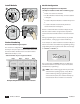
NOTE: 6-Station module is compatible only with the
ESP-Me. They are not backwards compatible with the
previous vintage controller.
NOTE: For ideal station sequencing, it is
recommended that a 6-Station module always
be installed in Bay 2. For more details see Station
Numbering section.
6
6
Installation
ESP-Me User Manual