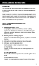
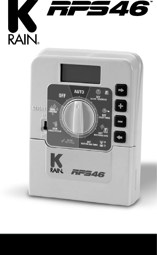
MINI IRRIGATION CONTROLLER www.krain.com Station Models - Available in 4 OR 6 stations. OUTdoor MODEL - Supplied with 120VAC x 24VAC inbuilt transformer. Optional LEAD with Plug.
Table Of Contents Features .......................................................................................... 1 Glossary .......................................................................................... 2 Programming Instructions .......................................................... 3 Introduction ......................................................................................... 3 Other Functions ...................................................................................
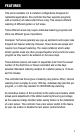
Features This unit is available in 4 & 6 station configurations Designed for residential applications, this controller has four separate programs with a maximum of sixteen start times a day. This ensures efficient watering of different garden or turf areas. These different areas may require individual watering programs and often use different types of sprinklers. Examples: Turf areas generally use pop-up sprinklers and require less frequent but heavier watering.
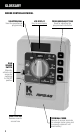
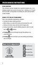
Glossary Indoor Controller Model Selection Dial Used for operations & programming LCD Display Easy to read display Programming Buttons Used for adjusting the programmed information Rain Sensor Switch Manually activate rain sensor by switching to ON/OFF position Fuse Location Remove cover to access fuse Terminal Cover Remove to access terminals for solenoid (valve) wires and to annually replace 9 volt block battery
Programming Instructions Introduction This controller has been designed with four separate program starts, to allow different garden areas to have their own individual watering requirements. A start is basically a method of grouping stations (valves) with similar watering requirements to water on the same days. These stations will water in sequential order from the lowest number at the start time (or times) nominated and on the days selected. The key elements when programming your controller are: 1.
Programming Instructions Other Functions This controller can also manually run a selected program once, or an individual station can be set to run once from 1 minute up to 12 hours and 59 minutes. A test facility for checking the valves and sprinklers is also provided. General tips for easy programming Tips to help eliminate programming confusion. Complete the spare watering planner. When setting, one push of the button will increment one unit. Holding one button down will fast scroll through units.
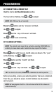
Programming Set Current Time & Correct Day Turn the dial to Set Clock/Calendar position. The hour will be flashing. Use or to adjust. Note: AM / PM must be set correctly. Press the Use or Press Use button and the “minutes” will flash. to adjust. and the “day of the week” will flash. or to set correct day. Set Calendar (Optional) Note: The calendar only needs to be set when selecting ODD/EVEN day watering in areas where water restrictions may require this feature.
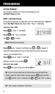
Programming Setting Program 1 The program number can only be set/changed in the Set Start Times position. STEP 1. Set Start Times All valves will activate in sequential order for each start time. Turn the dial to Set Start Times and ensure that “Prog 1” is flashing. The display will show: Press & “Start 1” willl flash. Press & the “hour” will flash. Use or to adjust. NOTE: AM / PM is set correctly. Press & the “minutes” will flash. Use or to adjust, if required.
Programming STEP 2. Set Watering Days This unit has interval watering or individual day selection from every day to every 15th day or a 365 day calendar with odd/even day selection in areas where water restrictions require this feature. Turn the dial to Set Watering Days. Interval Day Selection The display will show: “Interval 1” will be flashing. This means that watering will occur every day. To change the interval day, press the button.
Programming Odd / Even Day Selection (Optional) In some regions, users are only allowed to water on ODD dates if their house number is ODD, or on EVEN dates when their number is EVEN. This controller allows this to be done simply by setting the relevant selection of ODD or EVEN and setting the current date into the controller. If you require the ODD / EVEN day option, simply press the button until “ODD” is shown. Press the button and “EVEN” will be shown.
Programming STEP 3. Set Station Run Times. (Continued) To adjust the Run time in minutes press set the run time in hours, press To adjust use or , and use . To and “0” will appear and flash. . If not required, press station 2 by pressing the or and advance to button. Continue until all the stations in Program 1 have been set with a run time, or if a station (or stations) are not required to be active in this particular program, ensure that the run time is set to “OFF”.
Manual Operations System Test Facility Turn the dial to Run Test Cycle. There will be a two second pause. The display will show: Use this feature to check that your valves & sprinklers are working correctly. The unit will run all stations in sequential order. The factory preset time of 2 minutes per station can be adjusted. The new adjusted run time will become the new default time. TIP: If the water supply is from a pump system, it is critical to ensure all outputs are connected to a valve.
Manual Operations (cont.) Run A PROGRAM To manually run a complete program once for the run times as set in the automatic schedule turn the dial to the Run a Start position. “Prog 1” will be shown in the display. To run program 1, leave or advance to start 2 by pressing . Other Features Other Features Stop To stop an automatic or manual watering schedule, turn the dial to the Off position. TIP: For automatic watering, remember to turn the dial back to the Auto Run position.
Other Features Fitting a Rain Sensor (optional) A rain sensor can be wired directly into the terminal block. When the sensor is wet, all automatic and manual watering will not operate. To fit a rain sensor follow this procedure: 1. The sensor switch, accessed on the fascia, must be up in the “on” position. To over-ride the sensor when it is wet, simply move the sensor switch down to the “OFF” position. This will allow automatic and manual watering cycles to operate. 2. Connecting the rain sensor wires: A.
Other Features Rain Off Mode To stop the automatic watering cycles during winter, turn the dial to the Off position. The word “Off” will appear in the display. This means the automatic programs will not come on, but the programmed information is still retained in the memory. To reactivate the automatic schedule, turn the dial back to the Auto Run position. Water Budgeting The automatic station run times can be adjusted by percentage as the seasons change.
Installation Instructions Mounting The Controller This controller unit is an INDOOR MODEL and MUST not be exposed to rain or water ingress, or direct sunlight. Install the controller near a 120VAC outlet, preferably located in a house, garage or other covered area. For ease of operation, eye level placement is recommended. Drive one #8 screw into the wall, leaving about 4mm (1/8 inch ) of the screw exposed. If necessary, use a toggle bolt or masonary shield.
Installation Instructions Field Wiring Connections PREPARATION 1 Prepare wires for hook-up by cutting the wires to the correct length and stripping approximately 6mm (¼ inch) of insulation from the end to be connected to the controller. 2 Ensure terminal block screws are loosened sufficiently to permit easy access for wire ends. Insert stripped wire ends into the clamp aperture and tighten screws. Do not over tighten as this may damage the terminal block. 3 A maximum of 0.
Installation Instructions Power Supply Connections The controller itself can run off a 120VAC to 24V AC external transformer. It is recommended that the transformer is not connected to a 120VAC supply which is also servicing or supplying motors (i.e. Air conditioners, pool pumps, refrigerators, etc.) Lighting circuits are suitable as a power source.
Installation Instructions Pump Hook-Up Connections Do not attempt to drive a pump starter directly from the controller. Pump start is provided by connecting one side of the coil of a suitable relay to the Master Valve/Pump Start output of the controller and the other side to the controller common. For systems supplied with water from a pump, unused stations must be connected back to the last used station to eliminate the possibilty of the pump running against a closed head.
Electrical Characteristics Power Supply This unit can run off a 60Hz external transformer, (plug pack), with an output of 24VAC 60Hz @ 0.85 Amp. Plug Pack Model The correct wiring installation for the 24VAC plug pack is shown on page 16. The plug pack model is only suitable for indoor installation. Electrical Outputs Electrical Power Supply Input: 24Volts AC 60Hz. Electrical Outputs: Maximum of 0.85 AMPS To Solenoid Valves: 24 VAC 50/60 Hz 0.5 AMPs max. To the Master Valve/Pump Start: 24VAC 0.
Servicing The Controller The controller should always be serviced by an authorised agent. Follow these steps: 1. Turn power off to the controller. 2. Disconnect 24 Volt power leads from the plug pack at the controller 24VAC terminals. 3. Clearly mark or identify all valve wires according to the terminals they are connected to, (1 to 6). This allows you to easily wire them back to the controller, maintaining your valve watering sequence. 4. Disconnect valve wires from the terminal block. 5.
Troubleshooting Symptom Possible Cause Suggestion No display. Faulty transformer. Fuse blown. Check fuse. Check field wiring. Check transformer. Single Station not working. Faulty solenoid coil. Swap faulty station wire on controller terminal block with known working station wire. If the faulty valve still does not work on the known working connection then the solenoid coil is faulty. The panel may need to be repaired. Fuse blows. Incorrect wiring or bad wiring connection.
Spare Watering Planner 21
Notes 22
Notes 23
Guarantee The manufacturer Guarantees to the original purchaser that any product supplied by the manufacturer will be free from defects in materials and workmanship for a period of two years from the date of purchase. Any product found to have defects in material or workmanship within the period of this Guarantee shall be repaired or replaced by the manufacturer free of charge.