
Owner's manual
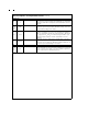

Pin Descriptions and Equivalent Circuits (Continued)
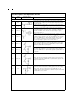
Digital Power
20 V
D
Positive digital supply pin. This pin should be connected to the same clean,
quiet +5V source as is V
A
and bypassed to DGND with a 0.1 µF monolithic
capacitor in parallel with a 10µF capacitor, both located within 1 cm of the
power pin.
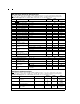
12,13
14,19,
41,42,
43
DGND
The ground return for the digital supply. AGND and DGND should be
connected together directly beneath the ADC14061 package. See Section
5 (Layout and Grounding) for more details.
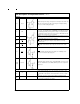
34 V
D
I/O
Positive digital supply pin for the ADC14061’s output drivers. This pin
should be connected to a +3V to +5V source and bypassed to DGND I/O
with a 0.1 µF monolithic capacitor. If the supply for this pin is different from
the supply used for V
A
and V
D
, it should also be bypassed with a 10 µF
capacitor. All bypass capacitors should be located within 1 cm of the
supply pin.
33 DGND I/O
The ground return for the digital supply for the ADC14061’s output drivers.
This pin should be connected to the system digital ground, but not be
connected in close proximity to the ADC14061’s DGND or AGND pins. See
Section 5.0 (Layout and Grounding) for more details.
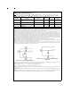
NC
2, 3,
9, 15,
16,
21,
22, 39
NC
All pins marked NC (no connect) should be left floating. Do not connect the
NC pins to ground, power supplies, or any other potential or signal. These
pins are used for test in the manufacturing process.
www.national.com5