
Manual


26
AT77C105A [Preliminary]
5419A–BIOM–01/05
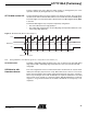
Example of Navigation
Registers
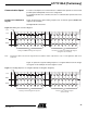
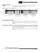
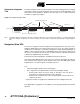
Figure 12 represents a typical reading sequence of the three navigation registers.
Refer to “Appendix C” on page 37 for flowchart
Figure 12. Reading of the Navigation Registers
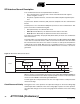
Image Capture (Fast SPI)
This serial interface enables full-speed acquisition of the sensor’s pixels by the host.
This interface only supports the serial clock (SCK) and one data line: MISO (Master In/
Slave Out).
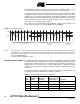
Communication Protocol When the sensor is in acquisition mode, the host can receive pixels through the fast SPI
(FSS/ = 0). The host must transmit the communication clock (SCK) to receive the pixels.
This clock must have a regular frequency to obtain constant fingerprint slices (See “Reg-
istration Integration Time” on page 30.).
With the sensor configured to acquisition mode, the controller can proceed to fast
accesses.
SCK
MISO
MOSI
Reading of Navigation
Register Requested
X X
X
X X X X
X
0 1 0
1
0 1 0
0 0 0
1
1 0 0 00
0 0 1 0 0 0 0
1
1
1
0 0 0 X X
1
X
X
X
X X X X
0
X
X
X XX
X
0
X
X X XX X X
0
X
Emission of the First
Navigation Register
(No Overflow, Y Negative Movement
Click Detected, Black Slice)
Emission of the Second
Navigation Register
(X Absolute Movement
= 24 Pixels)
Emission of the Third
Navigation Register
(Y Absolute Movement
= 144 Pixels)