
Manual


2
AT86RF401
1424D–RKE–09/02
In-system programmable, nonvolatile Flash program memory and EEPROM data stor-
age make possible rapid time-to-market and lower inventory costs.
Static current consumption is kept to a minimum with an ultra-low current shutdown
mode. Normal operation resumes when a button is pressed. This activates the crystal
oscillator circuit that serves as the clock for the AVR microcontroller.
The RF carrier is synthesized utilizing an on-board Voltage Controlled Oscillator (VCO).
Optimal tuning of the VCO is maintained over component tolerance through the use of a
software-controlled switched capacitor array. Its accuracy is maintained with a PLL
detector that compares the crystal oscillator to a frequency-scaled version (divided by
24) of the RF carrier. The resulting error signal adjusts the VCO to produce a very stable
RF carrier.
An interrupt-based bit-timer structure, integral to the AVR microcontroller, simplifies the
implementation of user-specific, data-bit encoding routines, such as PWM or Manches-
ter, for modulating the RF carrier. Thirty-six dB of RF power output control is available to
the user in 1 dB steps and is addressable in software. The RF signal output is placed
differentially on a tuned-loop antenna, which may be realized as a counterspread cop-
per trace on a PCB.
The AT86RF401 is fabricated in Atmel’s 0.6 µm Mixed Signal CMOS + EEPROM pro-
cess, enabling true system-level integration (SLI).
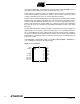
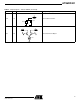
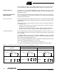
Figure 2. 20-lead TSSOP
1
2
3
4
5
6
7
8
9
10
ANTB
LOOPFIL
L1
L2
RESETB
N/C
I/O0 (SDI)
I/O1 (SDO)
I/O2 (SCK)
XTAL/CLK
20
19
18
17
16
15
14
13
12
11
ANT
CFIL
AVDD
DVDD
AGND
DGND
I/O5
I/O4
I/O3
XTALB