
Manual


33
AT86RF401
1424D–RKE–09/02
• Bits[7:6]: VCO Voltage Detector
The VCO Voltage Detector circuit monitors the level of the VCO control voltage. This cir-
cuit, along with the VCO Switch Caps and the Lock Detect circuit, is intended for use
with a software algorithm to tune the VCO such that the VCO control voltage is centered
approximately at 1.1V.
The Voltage Detector circuit consists of two comparators with fixed reference voltages
of V1 (lower reference voltage) and V2 (upper reference voltage). The VCO Control
Voltage is compared to these two reference voltages and generates the state table
listed in Table 8. The state of these comparators is output to Bits 7 and 6 (Vcodet[1:0])
of the VCOTUNE register.
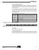
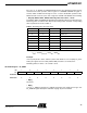
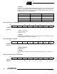
Lock Detector Configuration Register 2 – LOCKDET2
• Bit[7]: EUD
A “1” enables the unlock detect logic.
• Bit[6]: LAT (Lock Always True)
Forces the lockdetect signal to “1” at the output of the lock detect circuitry. This may be
useful if the lock detect signal is not going high for some reason, and a power amp inter-
lock has been implemented, and the user wishes to enable the power amp output stage.
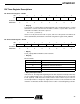
Table 8. VCO Window Comparator States
VCOvdet[1:0] VCO Control Voltage
00
Above lower comparator threshold and below upper comparator
threshold. Control Voltage is within the valid window of operation.
01
Below both thresholds. Control Voltage is outside the recommended
window of operation.
10
Above both thresholds. Control Voltage is outside the recommended
window of operation.
11 Not a valid state.
Bit 76543210
$17 EUD LAT ULC[2] ULC[1] ULC[0] LC[2] LC[1] LC[0]
Read/Write R/W R/W R/W R/W R/W R/W R/W R/W
Initial Value 00000000