
Manual


34
AT86RF401
1424D–RKE–09/02
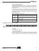
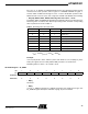
• Bit[5:3]: ULC[2:0]
The unlock count (ULC) bits count a certain number of reference clocks, after which the
unlock detect circuit looks for a number of cycle slips determined by CS[1:0] before
making the loc detect signal go low. The ULC bits essentially control the blackout period
of the unlock detect circuit. The unlock counter is reset by the KEY signal rising (if
ENKO is asserted), or by the LOC rising edge, or by the UPOK signal being set high.
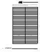
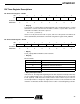
• Bits[2:0]: LC[2:0]
The Lock Count (LC) bits control a counter that, after a number of reference clocks,
cause lock detect to go high. This counter will reset if a cycle slip or a reset signal occurs
(which happens if TXE goes low), if an out-of-lock condition occurs, if the crystal oscilla-
tor frequency is too low, or if the VCO feedback frequency is too low.
ULC[2:0]
Number of REF
Clocks of Delay
000 8
001 16
010 32
011 64
100 128
101 256
110 512
111 1024
LC[2:0] Number of REF Clocks of Delay
000 8
001 16
010 32
011 64
100 128
101 256
110 512
111 1024