
User Manual


121
AT8xC5122/23
4202E–SCR–06/06
Reset Value = 0000 0000b
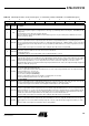
Table 70. USB Endpoint Status and Control Register X - UEPSTAX (S:CEh) X=EPNUM set in UEPNUM Register)
76543210
DIR RXOUTB1 STALLRQ TXRDY STL/CRC RXSETUP RXOUTB0 TXCMP
Bit
Number
Bit
Mnemonic Description
7DIR
Control Endpoint Direction
This bit is used only if the endpoint is configured in the control type (see“USB Endpoint X Control Register - UEPCONX (S:D4h)”
on page 120).
This bit determines the Control data and status direction.
The device firmware should set this bit ONLY for the IN data stage, before any other USB operation. Otherwise, the device
firmware should clear this bit.
6 RXOUTB1
Received OUT Data Bank 1 for Endpoint 6 (Ping-pong Mode)
This bit is set by hardware after a new packet has been stored in the endpoint FIFO Data bank 1 (only in Ping-pong mode).
Then, the endpoint interrupt is triggered if enabled (see “USB Global Interrupt Register - USBINT (S:BDh)” on page 118) and all
the following OUT packets to the endpoint bank 1 are rejected (NAK’ed) until this bit has been cleared, excepted for Isochronous
Endpoints.
This bit should be cleared by the device firmware after reading the OUT data from the endpoint FIFO.
5STALLRQ
Stall Handshake Request
Set this bit to request a STALL answer to the host for the next handshake.
Clear this bit otherwise.
For CONTROL endpoints: cleared by hardware when a valid SETUP PID is received.
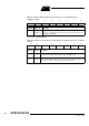
4 TXRDY
TX Packet Ready
Set this bit after a packet has been written into the endpoint FIFO for IN data transfers. Data should be written into the endpoint
FIFO only after this bit has been cleared. Set this bit without writing data to the endpoint FIFO to send a Zero Length Packet.
This bit is cleared by hardware, as soon as the packet has been sent for Isochronous endpoints, or after the host has
acknowledged the packet for Control, Bulk and Interrupt endpoints. When this bit is cleared, the endpoint interrupt is triggered if
enabled (see Table 65 on page 118).
3 STLCRC
Stall Sent / CRC error flag
- For Control, Bulk and Interrupt Endpoints:
This bit is set by hardware after a STALL handshake has been sent as requested by STALLRQ. Then, the endpoint interrupt is
triggered if enabled (see“” on page 118)
It should be cleared by the device firmware.
- For Isochronous Endpoints (Read-Only):
This bit is set by hardware if the last received data is corrupted (CRC error on data).
This bit is updated by hardware when a new data is received.
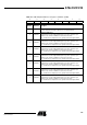
2 RXSETUP
Received SETUP
This bit is set by hardware when a valid SETUP packet has been received from the host. Then, all the other bits of the register
are cleared by hardware and the endpoint interrupt is triggered if enabled (see Table 65 on page 118).
It should be cleared by the device firmware after reading the SETUP data from the endpoint FIFO.
1 RXOUTB0
Received OUT Data Bank 0 (see also RXOUTB1 bit for Ping-pong Endpoints)
This bit is set by hardware after a new packet has been stored in the endpoint FIFO data bank 0. Then, the endpoint interrupt is
triggered if enabled (see“” on page 118) and all the following OUT packets to the endpoint bank 0 are rejected (NAK’ed) until this
bit has been cleared, excepted for Isochronous Endpoints. However, for control endpoints, an early SETUP transaction may
overwrite the content of the endpoint FIFO, even if its Data packet is received while this bit is set.
This bit should be cleared by the device firmware after reading the OUT data from the endpoint FIFO.
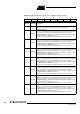
0TXCMPL
Transmitted IN Data Complete
This bit is set by hardware after an IN packet has been transmitted for Isochronous endpoints and after it has been accepted
(ACK’ed) by the host for Control, Bulk and Interrupt endpoints. Then, the endpoint interrupt is triggered if enabled (see Table
65).
This bit should be cleared by the device firmware before setting TXRDY.