
User Manual


181
AT8xC5122/23
4202E–SCR–06/06
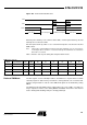
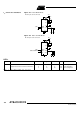
Figure 109. Power-down Exit Waveform
Exit from power-down by reset redefines all the SFRs, exit from power-down by external
interrupt does no affect the SFRs.
Exit from power-down by either reset or external interrupt does not affect the internal
RAM content.
Note: If idle mode is activated with power-down mode (IDL and PD bits set), the exit sequence
is unchanged, when execution is vectored to interrupt, PD and IDL bits are cleared and
idle mode is not entered.
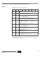
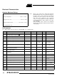
Table shows the state of ports during idle and power-down modes.
Note: 1. Port 0 can force a 0 level. A "one" will leave port floating.
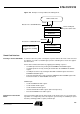
Reduced EMI Mode The ALE signal is used to demultiplex address and data buses on port 0 when used with
external program or data memory. Nevertheless, during internal code execution, ALE
signal is still generated. In order to reduce EMI, ALE signal can be disabled by setting
AO bit.
The AO bit is located in AUXR register at bit location 0. As soon as AO is set, ALE is no
longer output but remains active during MOVX and MOVC instructions and external
fetches. During ALE disabling, ALE pin is weakly pulled high.
INT1
INT0
XTAL1
Power-down phase Oscillator restart phase Active phaseActive phase
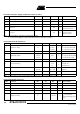
Table State of Ports
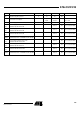
Mode Program Memory ALE PSEN P0 P1 P2 P3 P4 P5
Idle Internal 1 1 Port Data
(1)
Port Data Port Data Port Data Port Data Port Data
Idle External 1 1 Floating Port Data Address Port Data Port Data Port Data
Power-down Internal 0 0 Port Dat* Port Data Port Data Port Data Port Data Port Data
Power-down External 0 0 Floating Port Data Port Data Port Data Port Data Port Data