
User Manual


79
AT8xC5122/23
4202E–SCR–06/06
Reset Value = 0000 0000b
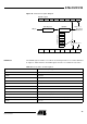
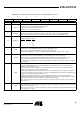
Table 44. Smart Card Interface Control Register - SCICR (S:B6h, SCRS = 1)
76543210
RESET CARDDET VCARD1 VCARD0 UART WTEN CREP CONV
Bit Number Bit Mnemonic Description
7 RESET
Reset
Set this bit to reset and deactivate the Smart Card Interface.
Clear this bit to activate the Smart Card Interface.
This bit acts as an active high software reset.
6 CARDDET
Card Presence Detector Sense
Clear this bit to indicate the card presence detector is open when no card is inserted (CPRES is high).
Set this bit to indicate the card presence detector is closed when no card is inserted (CPRES is low).
5-4 VCARD[1:0]
Card Voltage Selection:
VCARD[1]
VCARD[0] CVCC
00 0 V
01 1.8 V
10 3.0 V
1 1 5.0 V
3UART
Card UART Selection
Clear this bit to use the CARDIO bit (P1.0) bit to drive the Card I/O (P1.0) pin.
Set this bit to use the Smart Card UART to drive the Card I/O pin (P1.0 pin).
Controls also the Waiting Time Counter as described in Section “Waiting Time (WT) Counter”, page 69
2WTEN
Waiting Time Counter Enable
Clear this bit to stop the counter and enable the load of the Waiting Time counter hold registers.
The hold registers are loaded with SCWT0, SCWT1, SCWT2 and SCWT3 values when SCWT2 is written.
Set this bit to start the Waiting Time Counter. The counters stop when it reaches the timeout value.
If the UART bit is set, the Waiting Time Counter automatically reloads with the hold registers whenever a start bit is
sent or received.
1 CREP
Character Repetition
Clear this bit to disable parity error detection and indication on the Card I/O pin in receive mode and to disable
character repetition in transmit mode.
Set this bit to enable parity error indication on the Card I/O pin in receive mode and to set automatic character
repetition when a parity error is indicated in transmit mode.
Depending upon CREPSET bit is SCSR register, the receiver can indicate parity error up to 4times (3 repetitions) or
up to 5times (4 repetitions) after which it will raise the parity error bit SCPE bit in the SCISR register. If parity interrupt
is enabled, the SCPI bit in SCIIR register will be set too.
Alternately, the transmitter will detect ICC character repetition request. After 3 or 4 unsuccessful repetitions
(depending on CREPSEL bit in SCSR register), the transmitter will raise the parity error bit SCPE bit in the SCISR
register. If parity interrupt is enabled, the SCPI bit in SCIIR register will be set too.
Note : Character repetition mode is specified for T=0 protocol only and should not be used in T=1 protocol (block
oriented protocol)
0CONV
ISO Convention
Clear this bit to use the direct convention: b0 bit (LSB) is sent first, the parity bit is added after b7 bit and a low level
on the Card I/O pin represents a’0’.
Set this bit to use the inverse convention: b7 bit (LSB) is sent first, the parity bit is added after b0 bit and a low level on
the Card I/O pin represents a’1’.