Features • Protocol – USB Used as a Physical Layer – Device Firmware Upgrade Class Compliant – Auto-Frequency Detection • In-System Programming – Read/Write Flash Memory – Read Device ID – Full-chip Erase – Read/Write Configuration Bytes – Security Setting from ISP Command – Remote Application Start Command • In-Application Programming/Self-Programming – Read/Write Flash Memory – Read Device ID – Block Erase – Read/Write Configuration Bytes – Bootloader Start USB Microcontrollers AT89C5132 USB Bootloader
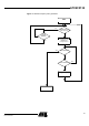
Functional Description The AT89C5132 USB Bootloader facilitates In-System Programming (ISP) and In-Application Programming (IAP) . In-System Programming Capability In-System Programming allows the user to program or reprogram the microcontroller on-chip Flash memory without removing it from the system and without the need of a pre-programmed application. The USB bootloader can manage a communication with a host through the USB bus.
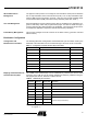
AT89C5132 ISP Communication Management The purpose of this process is to manage the communication and its protocol between the on-chip bootloader and an external device (host). The on-chip bootloader implements a USB protocol (see Section “Protocol”, page 10). This process translates serial communication frames (USB) into Flash memory accesses (read, write, erase...).
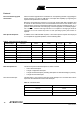
Security The bootloader has Software Security Byte (SSB) to protect itself from user access or ISP access. The Software Security Byte (SSB) protects from ISP accesses. The command ’Program Software Security Bit’ can only write a higher priority level. There are three levels of security: • Level 0: NO_SECURITY (FFh) This is the default level. From level 0, one can write level 1 or level 2. • Level 1: WRITE_SECURITY (FEh) In this level it is impossible to write in the Flash memory.
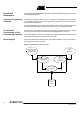
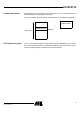
AT89C5132 Software Boot Vector The Software Boot Vector (SBV) forces the execution of a user bootloader starting at address [SBV]00h in the application area (FM0). The way to start this user bootloader is described in Section “Bootloader Configuration”. USB Bootloader User Bootloader [SBV]00h Application FM1 FM0 FLIP Software Program FLIP is a PC software program running under Windows® 9x/Me/2000/XP and LINUX® that supports all Atmel Flash microcontrollers and USB protocol communication media.
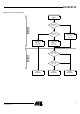
In-System Programming The ISP allows the user to program or reprogram the microcontroller’s on-chip Flash memory through the serial line without removing it from the system and without the need of a pre-programmed application. This section describes how to start the UART bootloader and the higher level protocol over the serial line.
AT89C5132 Figure 2.
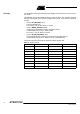
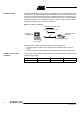
Physical Layer The USB norm specifies all the transfers over the USB line. The USB specification also includes several CLASS and SUB-CLASS specifications. These stand-alone documents are used by the manufacturer to implement a USB link between a PC and a device supporting the In-System Programming. Mostly, the USB specification is implemented by hardware (automatic reply, handshakes, timings, ...) and the USB Classes and SubClasses are implemented by software at a data level. Figure 3.
AT89C5132 Figure 4.
Protocol Device Firmware Upgrade Introduction Device Firmware Upgrade is the mechanism for accomplishing the task of upgrading the device firmware. Any class of USB device can exploit this capability by supporting the requirements specified in this document. Because it is impractical for a device to concurrently perform both DFU operations and its normal run-time activities, those normal activities must cease for the duration of the DFU operations.
AT89C5132 Table 6.
Note: 1. Alternate settings can be used by an application to access additional memory segments. In this case, it is suggested that each alternate setting employs a string descriptor to indicate the target memory segment; e.g., “EEPROM”. Details concerning other possible uses of alternate settings are beyond the scope of this document. However, their use is intentionally not restricted because it is anticipated that implementers will devise additional creative uses for alternate settings.
AT89C5132 Device Status Get Status The Host employs the DFU_GETSTATUS request to facilitate synchronization with the device. This status gives information on the execution of the previous request: in progress/OK/Fail/...
Table 10. bStatus Values (Continued) Status Value Description errPOR 0x0D Device detected unexpected power on reset errUNKNOWN 0x0E Something went wrong, but the device does not know what it was errSTALLEDPK 0x0F Device stalled an unexpected request Table 11.
AT89C5132 DFU_ABORT Request Programming the Flash The DFU_ABORT request enables the device to exit from certain states and return to the DFU_IDLE state. The device sets the OK status on receipt of this request. For more information, see the corresponding state transition summary. bmRequestType bRequest wValue wIndex wLength Data 1010 0001b DFU_ABORT (6) Zero Interface (4) 0 None The firmware image is downloaded via control-write transfers initiated by the DFU_DNLOAD class-specific request.
Request from Host bmRequestType bRequest wValue wIndex wLength Data 0010 0001b DFU_DNLOAD (1) wBlock Interface (4) Length Firmware Write Command Command Identifier data[0] Id_prog_start 01h 00h data[1] data[2] start_address data[3] data[4] end_address Description Init Flash programming The write command is 6 bytes long. In order to reach the USB specification of the Control type transfers, the write command is completed with 26 (=32-6) non-significant bytes.
AT89C5132 Answers from Bootloader After each program request, the Host can request the device state and status by sending a DFU_GETSTATUS message. If the device status indicates an error, the host can send a DFU_CLRSTATUS request to the device. Reading the Flash The flow described below allows the user to read data in the Flash memory. A blank check command on the Flash memory is possible with this flow. This operation is performed in 2 steps: 1. DFU_DNLOAD request with the read command (6 bytes) 2.
Answers from the Device to a Blank Check Command 18 The Host controller send a GET_STATUS request to the device. Once internal blank check has been completed, the device sends its status. • If the device status is “OK”: the device memory is then blank and the device waits the next Host request. • If the device status is “errCHECK_ERASED”: the device memory is not blank. The device waits for an DFU_UPLOAD request to send the first address where the byte is not 0xFF.
AT89C5132 Programming Configuration Information The flow described below allows the user to program Configuration Information regarding the bootloader functionality. • Boot Process Configuration: – BSB – SBV – Fuse bits (BLJB, X2) (see Section “Mapping and Default Value of Hardware Security Byte”, page 3) Ensure that the Program Fuse bit command programs the 4 Fuse bits at the same time.
Reading Configuration Information or Manufacturer Information The flow described below allows the user to read the configuration or manufacturer information. Requests from Host To start the programming operation, the Host sends DFU_DNLOAD request with the Read command in the data field (2 bytes).
AT89C5132 Answers from Bootloader The device has two possible answers to a DFU_GETSTATUS request: • If the chip is protected from program access, a “err_VENDOR” status is returned to the Host. • Otherwise, the device status is “OK“. The Host can send a DFU_UPLOAD request to the device in order the value of the requested field.
Erasing the Flash The flow described below allows the user to erase the Flash memory. Two modes of Flash erasing are possible: • Full chip erase • Block erase The Full Chip erase command erases the whole Flash (32 Kbytes) and sets some Configuration Bytes at their default values: • BSB = FFh • SBV = FFh • SSB = FFh (NO_SECURITY) The Block erase command erases only a part of the Flash.
AT89C5132 Starting the Application The flow described below allows to start the application directly from the bootloader upon a specific command reception. Two options are possible: • Start the application with a reset pulse generation (using watchdog). When the device receives this command the watchdog is enabled and the bootloader enters a waiting loop until the watchdog resets the device.
In-Application Programming/SelfProgramming The IAP allows to reprogram the microcontroller on-chip Flash memory without removing it from the system and while the embedded application is running. The user application can call Application Programming Interface (API) routines allowing IAP. These API are executed by the bootloader. To call the corresponding API, the user must use a set of Flash_api routines which can be linked with the application.
AT89C5132 API Commands Read/Program Flash Memory Several types of APIs are available: • Read/Program Flash memory • Read Configuration and Manufacturer Information • Program Configuration Information • Erase Flash • Start bootloader To read the Flash memory the bootloader is not involved. For more details on these routines see the AT89C5132 Datasheet, section “Program/Code Memory”.
Read Configuration and Manufacturer Information • Parameter settings API Name api_command api_dph api_dpl api_value __api_rd_HSB 08h – 00h return HSB __api_rd_BSB 05h – 00h return BSB __api_rd_SBV 05h – 01h return SBV __api_rd_SSB 05h – 05h return SSB __api_rd_EB 05h – 06h return EB __api_rd_manufacturer 05h – 30h return manufacturer id __api_rd_device_id1 05h – 31h return id1 __api_rd_device_id2 05h – 60h return id2 __api_rd_device_id3 05h – 61h return id
AT89C5132 Program Configuration Information • Parameter settings API Name api_command api_dph api_dpl __api_clr_BLJB 07h – – __api_set_BLJB 07h – – __api_clr_X2 07h – – __api_set_X2 07h – – HSB & 7Fh __api_wr_BSB 04h – 00h value to write __api_wr_SBV 04h – 01h value to write __api_wr_SSB 04h – 05h value to write __api_wr_EB 04h – 06h value to write • (HSB & BFh) | 40h HSB & BFh (HSB & 7Fh) | 80h instruction: LCALL FFF0h. Notes: Erasing the Flash api_value 1.
Appendix-A Table 13.
AT89C5132 Table 14.
Appendix-B Table 17.
Atmel Corporation 2325 Orchard Parkway San Jose, CA 95131 Tel: 1(408) 441-0311 Fax: 1(408) 487-2600 Regional Headquarters Europe Atmel Sarl Route des Arsenaux 41 Case Postale 80 CH-1705 Fribourg Switzerland Tel: (41) 26-426-5555 Fax: (41) 26-426-5500 Asia Room 1219 Chinachem Golden Plaza 77 Mody Road Tsimshatsui East Kowloon Hong Kong Tel: (852) 2721-9778 Fax: (852) 2722-1369 Japan 9F, Tonetsu Shinkawa Bldg.