
Manual
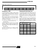

AT89LS53
4-254
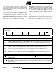
User software should not write 1s to these unlisted loca-
tions, since they may be used in future products to invoke
new features. In that case, the reset or inactive values of the
new bits will always be 0.
Timer 2 Registers
Control and status bits are contained in
registers T2CON (shown in Table 2) and T2MOD (shown in
Table 9) for Timer 2. The register pair (RCAP2H, RCAP2L)
are the Capture/Reload registers for Timer 2 in 16 bit cap-
ture mode or 16-bit auto-reload mode.
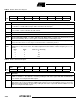
Watchdog Control Register
The WCON register contains
control bits for the Watchdog Timer (shown in Table 3). The
DPS bit selects one of two DPTR registers available.
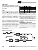
SPI Registers
Control and status bits for the Serial Periph-
eral Interface are contained in registers SPCR (shown in
Table 4) and SPSR (shown in Table 5). The SPI data bits
are contained in the SPDR register. Writing the SPI data
register during serial data transfer sets the Write Collision
bit, WCOL, in the SPSR register. The SPDR is double buff-
ered for writing and the values in SPDR are not changed by
Reset.
Interrupt Registers
The global interrupt enable bit and the
individual interrupt enable bits are in the IE register. In addi-
tion, the individual interrupt enable bit for the SPI is in the
SPCR register. Two priorities can be set for each of the six
interrupt sources in the IP register.
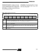
Table 2.
T2CON—Timer/Counter 2 Control Register
T2CON Address = 0C8H Reset Value = 0000 0000B
Bit Addressable
TF2 EXF2 RCLK TCLK EXEN2 TR2 C/T2
CP/RL2
Bit76543210
Symbol Function
TF2
Timer 2 overflow flag set by a Timer 2 overflow and must be cleared by software. TF2 will not be set when
either RCLK = 1 or TCLK = 1.
EXF2
Timer 2 external flag set when either a capture or reload is caused by a negative transition on T2EX and
EXEN2 = 1. When Timer 2 interrupt is enabled, EXF2 = 1 will cause the CPU to vector to the Timer 2 interrupt
routine. EXF2 must be cleared by software. EXF2 does not cause an interrupt in up/down counter mode
(DCEN = 1).
RCLK
Receive clock enable. When set, causes the serial port to use Timer 2 overflow pulses for its receive clock in
serial port Modes 1 and 3. RCLK = 0 causes Timer 1 overflows to be used for the receive clock.
TCLK
Transmit clock enable. When set, causes the serial port to use Timer 2 overflow pulses for its transmit clock in
serial port Modes 1 and 3. TCLK = 0 causes Timer 1 overflows to be used for the transmit clock.
EXEN2
Timer 2 external enable. When set, allows a capture or reload to occur as a result of a negative transition on
T2EX if Timer 2 is not being used to clock the serial port. EXEN2 = 0 causes Timer 2 to ignore events at
T2EX.
TR2 Start/Stop control for Timer 2. TR2 = 1 starts the timer.
C/T2
Timer or counter select for Timer 2. C/T2 = 0 for timer function. C/T2 = 1 for external event counter (falling
edge triggered).
CP/RL2
Capture/Reload select. CP/RL2 = 1 causes captures to occur on negative transitions at T2EX if EXEN2 = 1.
CP/RL2
= 0 causes automatic reloads to occur when Timer 2 overflows or negative transitions occur at T2EX
when EXEN2 = 1. When either RCLK or TCLK = 1, this bit is ignored and the timer is forced to auto-reload on
Timer 2 overflow.