
Manual


21
AT90S/LS8535
1041H–11/01
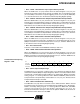
The most typical and general program setup for the Reset and Interrupt vector
addresses are:
Address Labels Code Comments
$000 rjmp RESET ; Reset Handler
$001 rjmp EXT_INT0 ; IRQ0 Handler
$002 rjmp EXT_INT1 ; IRQ1 Handler
$003 rjmp TIM2_COMP ; Timer2 Compare Handler
$004 rjmp TIM2_OVF ; Timer2 Overflow Handler
$005 rjmp TIM1_CAPT ; Timer1 Capture Handler
$006 rjmp TIM1_COMPA ; Timer1 CompareA Handler
$007 rjmp TIM1_COMPB ; Timer1 CompareB Handler
$008 rjmp TIM1_OVF ; Timer1 Overflow Handler
$009 rjmp TIM0_OVF ; Timer0 Overflow Handler
$00a rjmp SPI_STC; ; SPI Transfer Complete Handler
$00b rjmp UART_RXC ; UART RX Complete Handler
$00c rjmp UART_DRE ; UDR Empty Handler
$00d rjmp UART_TXC ; UART TX Complete Handler
$00e rjmp ADC ; ADC Conversion Complete Interrupt
Handler
$00f rjmp EE_RDY ; EEPROM Ready Handler
$010 rjmp ANA_COMP ; Analog Comparator Handler
$011 MAIN: ldi r16, high(RAMEND); Main program start
$012 out SPH,r16
$013 ldi r16, low(RAMEND) ;
$014 out SPL,r16
$015 <instr> xxx
…… ……
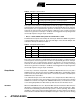
Reset Sources The AT90S8535 has three sources of reset:
• Power-on Reset. The MCU is reset when the supply voltage is below the Power-on
Reset threshold (V
POT
).
• External Reset. The MCU is reset when a low level is present on the RESET pin for
more than 50 ns.
• Watchdog Reset. The MCU is reset when the Watchdog timer period expires and
the Watchdog is enabled.
During reset, all I/O registers are set to their initial values and the program starts execu-
tion from address $000. The instruction placed in address $000 must be an RJMP
(relative jump) instruction to the reset handling routine. If the program never enables an
interrupt source, the interrupt vectors are not used and regular program code can be
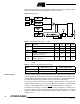
13 $00C UART, UDRE UART Data Register Empty
14 $00D UART, TX UART, Tx Complete
15 $00E ADC ADC Conversion Complete
16 $00F EE_RDY EEPROM Ready
17 $010 ANA_COMP Analog Comparator
Table 2. Reset and Interrupt Vectors (Continued)
Vector No. Program Address Source Interrupt Definition