
Manual


24
AT90S/LS8535
1041H–11/01
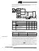
Watchdog Reset When the Watchdog times out, it will generate a short reset pulse of 1 XTAL cycle dura-
tion. On the falling edge of this pulse, the delay timer starts counting the Time-out period
t
TOUT
. Refer to page 49 for details on operation of the Watchdog.
Figure 27. Watchdog Reset during Operation
MCU Status Register –
MCUSR
The MCU Status Register provides information on which reset source caused an MCU
reset.
• Bits 7..2 – Res: Reserved Bits
These bits are reserved bits in the AT90S8535 and always read as zero.
• Bit 1 – EXTRF: External Reset Flag
After a power-on reset, this bit is undefined (X). It can only be set by an External Reset.
A Watchdog Reset will leave this bit unchanged. The bit is cleared by writing a logical
zero to the bit.
• Bit 0 – PORF: Power-on Reset Flag
This bit is only set by a Power-on Reset. A Watchdog Reset or an External Reset will
leave this bit unchanged. The bit is cleared by writing a logical zero to the bit.
To summarize, Table 5 shows the value of these two bits after the three modes of reset.
To make use of these bits to identify a reset condition, the user software should clear
both the PORF and EXTRF bits as early as possible in the program. Checking the
PORF and EXTRF values is done before the bits are cleared. If the bit is cleared before
an External or Watchdog Reset occurs, the source of reset can be found by using Table
6.
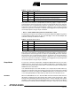
Bit 76543210
$34 ($54) ––––––EXTRF PORF MCUSR
Read/WriteRRRRRRR/WR/W
Initial Value000000See Bit Description
Table 5. PORF and EXTRF Values after Reset
Reset Source EXTRF PORF
Power-on Reset Undefined 1
External Reset 1 Unchanged
Watchdog Reset Unchanged Unchanged