
Manual


27
AT90S/LS8535
1041H–11/01
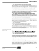
• Bit 5 – TICIE1: Timer/Counter1 Input Capture Interrupt Enable
When the TICIE1 bit is set (one) and the I-bit in the Status Register is set (one), the
Timer/Counter1 Input Capture Event Interrupt is enabled. The corresponding interrupt
(at vector $005) is executed if a capture-triggering event occurs on pin 20, PD6 (ICP)
(i.e., when the ICF1 bit is set in the Timer/Counter Interrupt Flag Register [TIFR]).
• Bit 4 – OCIE1A: Timer/Counter1 Output CompareA Match Interrupt Enable
When the OCIE1A bit is set (one) and the I-bit in the Status Register is set (one), the
Timer/Counter1 CompareA Match interrupt is enabled. The corresponding interrupt (at
vector $006) is executed if a CompareA match in Timer/Counter1 occurs (i.e., when the
OCF1A bit is set in the Timer/Counter Interrupt Flag Register [TIFR]).
• Bit 3 – OCIE1B: Timer/Counter1 Output CompareB Match Interrupt Enable
When the OCIE1B bit is set (one) and the I-bit in the Status Register is set (one), the
Timer/Counter1 CompareB Match interrupt is enabled. The corresponding interrupt (at
vector $007) is executed if a CompareB match in Timer/Counter1 occurs (i.e., when the
OCF1B bit is set in the Timer/Counter Interrupt Flag Register [TIFR]).
• Bit 2 – TOIE1: Timer/Counter1 Overflow Interrupt Enable
When the TOIE1 bit is set (one) and the I-bit in the Status Register is set (one), the
Timer/Counter1 Overflow Interrupt is enabled. The corresponding interrupt (at vector
$008) is executed if an overflow in Timer/Counter1 occurs (i.e., when the TOV1 bit is set
in the Timer/Counter Interrupt Flag Register [TIFR]).
• Bit 1 – Res: Reserved Bit
This bit is a reserved bit in the AT90S8535 and always reads zero.
• Bit 0 – TOIE0: Timer/Counter0 Overflow Interrupt Enable
When the TOIE0 bit is set (one) and the I-bit in the Status Register is set (one), the
Timer/Counter0 Overflow Interrupt is enabled. The corresponding interrupt (at vector
$009) is executed if an overflow in Timer/Counter0 occurs (i.e., when the TOV0 bit is set
in the Timer/Counter Interrupt Flag Register [TIFR]).
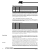
Timer/Counter Interrupt Flag
Register – TIFR
• Bit 7 – OCF2: Output Compare Flag 2
The OCF2 bit is set (one) when compare match occurs between the Timer/Counter2
and the data in OCR2 (Output Compare Register2). OCF2 is cleared by hardware when
executing the corresponding interrupt handling vector. Alternatively, OCF2 is cleared by
writing a logical “1” to the flag. When the I-bit in SREG and OCIE2 (Timer/Counter2
Compare Match Interrupt Enable) and the OCF2 are set (one), the Timer/Counter2
Compare Match Interrupt is executed.
• Bit 6 – TOV2: Timer/Counter2 Overflow Flag
The TOV2 bit is set (one) when an overflow occurs in Timer/Counter2. TOV2 is cleared
by hardware when executing the corresponding interrupt handling vector. Alternatively,
TOV2 is cleared by writing a logical “1” to the flag. When the SREG I-bit and TOIE2
(Timer/Counter2 Overflow Interrupt Enable) and TOV2 are set (one), the
Timer/Counter2 Overflow Interrupt is executed. In up/down PWM mode, this bit is set
when Timer/Counter1 advances from $0000.
Bit 7 6 5 4 3 2 1 0
$38 ($58) OCF2 TOV2 ICF1 OCF1A OCF1B TOV1 – TOV0 TIFR
Read/Write R/W R/W R/W R/W R/W R/W R R/W
Initial Value 0 0 0 0 0 0 0 0