
Manual


28
AT90S/LS8535
1041H–11/01
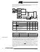
• Bit 5 – ICF1: Input Capture Flag 1
The ICF1 bit is set (one) to flag an input capture event, indicating that the
Timer/Counter1 value has been transferred to the Input Capture Register (ICR1). ICF1
is cleared by hardware when executing the corresponding interrupt handling vector.
Alternatively, ICF1 is cleared by writing a logical “1” to the flag. When the SREG I-bit
and TICIE1 (Timer/Counter1 Input Capture Interrupt Enable) and ICF1 are set (one), the
Timer/Counter1 Capture Interrupt is executed.
• Bit 4 – OCF1A: Output Compare Flag 1A
The OCF1A bit is set (one) when compare match occurs between the Timer/Counter1
and the data in OCR1A (Output Compare Register 1A). OCF1A is cleared by hardware
when executing the corresponding interrupt handling vector. Alternatively, OCF1A is
cleared by writing a logical “1” to the flag. When the I-bit in SREG and OCIE1A
(Timer/Counter1 Compare Match InterruptA Enable) and the OCF1A are set (one), the
Timer/Counter1 Compare A Match Interrupt is executed.
• Bit 3 – OCF1B: Output Compare Flag 1B
The OCF1B bit is set (one) when compare match occurs between the Timer/Counter1
and the data in OCR1B (Output Compare Register 1B). OCF1B is cleared by hardware
when executing the corresponding interrupt handling vector. Alternatively, OCF1B is
cleared by writing a logical “1” to the flag. When the I-bit in SREG and OCIE1B
(Timer/Counter1 Compare Match InterruptB Enable) and the OCF1B are set (one), the
Timer/Counter1 Compare Match B Interrupt is executed.
• Bit 2 – TOV1: Timer/Counter1 Overflow Flag
The TOV1 is set (one) when an overflow occurs in Timer/Counter1. TOV1 is cleared by
hardware when executing the corresponding interrupt handling vector. Alternatively,
TOV1 is cleared by writing a logical “1” to the flag. When the I-bit in SREG and TOIE1
(Timer/Counter1 Overflow Interrupt Enable) and TOV1 are set (one), the
Timer/Counter1 Overflow Interrupt is executed. In up/down PWM mode, this bit is set
when Timer/Counter1 advances from $0000.
• Bit 1 – Res: Reserved Bit
This bit is a reserved bit in the AT90S8535 and always reads zero.
• Bit 0 – TOV0: Timer/Counter0 Overflow Flag
The bit TOV0 is set (one) when an overflow occurs in Timer/Counter0. TOV0 is cleared
by hardware when executing the corresponding interrupt handling vector. Alternatively,
TOV0 is cleared by writing a logical “1” to the flag. When the SREG I-bit and TOIE0
(Timer/Counter0 Overflow Interrupt Enable) and TOV0 are set (one), the
Timer/Counter0 Overflow Interrupt is executed. In up/down PWM mode, this bit is set
when Timer/Counter1 advances from $0000.
External Interrupts The external interrupts are triggered by the INT1 and INT0 pins. Observe that, if
enabled, the interrupts will trigger even if the INT0/INT1 pins are configured as outputs.
This feature provides a way of generating a software interrupt. The external interrupts
can be triggered by a falling or rising edge or a low level. This is set up as indicated in
the specification for the MCU Control Register (MCUCR). When the external interrupt is
enabled and is configured as level-triggered, the interrupt will trigger as long as the pin
is held low.
The external interrupts are set up as described in the specification for the MCU Control
Register (MCUCR).