
Manual


30
AT90S/LS8535
1041H–11/01
The value on the INT pin is sampled before detecting edges. If edge interrupt is
selected, pulses that last longer than one CPU clock period will generate an interrupt.
Shorter pulses are not guaranteed to generate an interrupt. If low-level interrupt is
selected, the low level must be held until the completion of the currently executing
instruction to generate an interrupt. If enabled, a level-triggered interrupt will generate
an interrupt request as long as the pin is held low.
• Bit 1, 0 – ISC01, ISC00: Interrupt Sense Control 0 Bits 1 and 0
The External Interrupt 0 is activated by the external pin INT0 if the SREG I-flag and the
corresponding interrupt mask is set. The level and edges on the external INT0 pin that
activate the interrupt are defined in Table 9.
The value on the INT pin is sampled before detecting edges. If edge interrupt is
selected, pulses that last longer than one CPU clock period will generate an interrupt.
Shorter pulses are not guaranteed to generate an interrupt. If low-level interrupt is
selected, the low level must be held until the completion of the currently executing
instruction to generate an interrupt. If enabled, a level-triggered interrupt will generate
an interrupt request as long as the pin is held low.
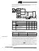
Sleep Modes To enter any of the three sleep modes, the SE bit in MCUCR must be set (one) and a
SLEEP instruction must be executed. The SM0 and SM1 bits in the MCUCR register
select which sleep mode (Idle, Power-down or Power Save) will be activated by the
SLEEP instruction. See Table 7.
If an enabled interrupt occurs while the MCU is in a sleep mode, the MCU wakes up,
executes the interrupt routine and resumes execution from the instruction following
SLEEP. The contents of the register file, SRAM and I/O memory are unaltered. If a reset
occurs during Sleep Mode, the MCU wakes up and executes from the Reset vector.
Idle Mode When the SM1/SM0 bits are set to 00, the SLEEP instruction makes the MCU enter the
Idle Mode, stopping the CPU but allowing SPI, UARTs, Analog Comparator, ADC,
Timer/Counters, Watchdog and the interrupt system to continue operating. This enables
the MCU to wake up from external triggered interrupts as well as internal ones like the
Timer Overflow and UART Receive Complete interrupts. If wake-up from the Analog
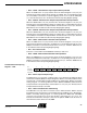
Table 8. Interrupt 1 Sense Control
ISC11 ISC10 Description
0 0 The low level of INT1 generates an interrupt request.
01Reserved
1 0 The falling edge of INT1 generates an interrupt request.
1 1 The rising edge of INT1 generates an interrupt request.
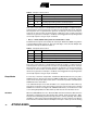
Table 9. Interrupt 0 Sense Control
ISC01 ISC00 Description
0 0 The low level of INT0 generates an interrupt request.
01Reserved
1 0 The falling edge of INT0 generates an interrupt request.
1 1 The rising edge of INT0 generates an interrupt request.