
Manual

5
AT90S/LS8535
1041H–11/01
current if the pull-up resistors are activated. Two Port C pins can alternatively be used
as oscillator for Timer/Counter2.
The Port C pins are tri-stated when a reset condition becomes active, even if the clock is
not running.
Port D (PD7..PD0) Port D is an 8-bit bi-directional I/O port with internal pull-up resistors. The Port D output
buffers can sink 20 mA. As inputs, Port D pins that are externally pulled low will source
current if the pull-up resistors are activated.
Port D also serves the functions of various special features of the AT90S8535 as listed
on page 86.
The Port D pins are tri-stated when a reset condition becomes active, even if the clock is
not running.
RESET
Reset input. An external reset is generated by a low level on the RESET pin. Reset
pulses longer than 50 ns will generate a reset, even if the clock is not running. Shorter
pulses are not guaranteed to generate a reset.
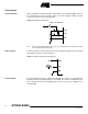
XTAL1 Input to the inverting oscillator amplifier and input to the internal clock operating circuit.
XTAL2 Output from the inverting oscillator amplifier.
AVCC AVCC is the supply voltage pin for Port A and the A/D Converter. If the ADC is not used,
this pin must be connected to VCC. If the ADC is used, this pin must be connected to
VCC via a low-pass filter. See page 68 for details on operation of the ADC.
AREF AREF is the analog reference input for the A/D Converter. For ADC operations, a volt-
age in the range 2V to AV
CC
must be applied to this pin.
AGND Analog ground. If the board has a separate analog ground plane, this pin should be con-
nected to this ground plane. Otherwise, connect to GND.