
Manual

6
AT90S/LS8535
1041H–11/01
Clock Options
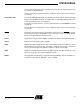
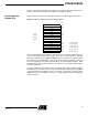
Crystal Oscillator XTAL1 and XTAL2 are input and output, respectively, of an inverting amplifier which can
be configured for use as an on-chip oscillator, as shown in Figure 2. Either a quartz
crystal or a ceramic resonator may be used.
Figure 2. Oscillator Connections
Note: When using the MCU Oscillator as a clock for an external device, an HC buffer should be
connected as indicated in the figure.
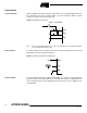
External Clock To drive the device from an external clock source, XTAL2 should be left unconnected
while XTAL1 is driven as shown in Figure 3.
Figure 3. External Clock Drive Configuration
Timer Oscillator For the Timer Oscillator pins, TOSC1 and TOSC2, the crystal is connected directly
between the pins. No external capacitors are needed. The oscillator is optimized for use
with a 32,768 Hz watch crystal. Applying an external clock source to TOSC1 is not
recommended.
XTAL2
XTAL1
GND
C2
C1
MAX 1 HC BUFFER
HC