Features • Incorporates the ARM926EJ-S™ ARM® Thumb® Processor • • • • • • • • • • – DSP Instruction Extensions, ARM Jazelle® Technology for Java® Acceleration – 16 Kbyte Data Cache, 16 Kbyte Instruction Cache, Write Buffer – 220 MIPS at 200 MHz – Memory Management Unit – EmbeddedICE™ In-circuit Emulation, Debug Communication Channel Support Additional Embedded Memories – One 32 Kbyte Internal ROM, Single-cycle Access at Maximum Matrix Speed – One 32 Kbyte Internal SRAM, Single-cycle Access at Max
• • • • • • • • • • • • • • • 2 – Four 32-bit Battery Backup Registers for a Total of 16 Bytes – Clock Generator and Power Management Controller – Advanced Interrupt Controller and Debug Unit – Periodic Interval Timer, Watchdog Timer and Real-Time Timer Reset Controller (RSTC) – Based on Two Power-on Reset Cells, Reset Source Identification and Reset Output Control Shutdown Controller (SHDC) – Programmable Shutdown Pin Control and Wake-up Circuitry Clock Generator (CKGR) – 32,768 Hz Low-power Oscil
AT91CAP9S500A/AT91CAP9S250A • One AC97 Controller (AC97C) – 6-channel Single AC97 Analog Front End Interface, Slot Assigner • Three Universal Synchronous/Asynchronous Receiver Transmitters (USART) • • • • • • • – Individual Baud Rate Generator, IrDA® Infrared Modulation/Demodulation, Manchester Encoding/Decoding – Support for ISO7816 T0/T1 Smart Card, Hardware Handshaking, RS485 Support Two Master/Slave Serial Peripheral Interface (SPI) – 8- to 16-bit Programmable Data Length, Four External Peripheral
NRST VDDCORE VDDBU SHDN WKUP XIN32 XOUT32 OSC XIN XOUT MCI0 MCI1 PDC POR POR OSC PIT RSTC SHDC RTT 4 GPREG PLLB PLLRCB MCI0_, MCI_1 TWI PDC FIFO PIOD PIOC PIOB PIOA PDC USART0 USART1 USART2 DMA CAN ROM 32Kbytes DMA USB OHCI SPI0 SPI1 PDC SRAM 32Kbytes DMA Image Sensor Interface PWMC Peripheral Bridge TC0 TC1 TC2 FIFO DMA LUT LCD Controller DMA FIFO AC97C PDC 23-channel Peripheral DMA PDC PDC 8-channel 10-bit ADC 4-channel DMA SSC0 SSC1 APB 12-layer Matr
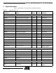
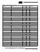
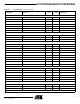
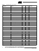
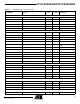
AT91CAP9S500A/AT91CAP9S250A 3. Signal Description Table 3-1 gives details on the signal name classified by peripheral. Table 3-1. Signal Description List Signal Name Function Type Active Level Comments Power Supplies VDDIOM EBI I/O Lines Power Supply Power 1.65V to 3.6V VDDIOP0 Peripherals I/O Lines Power Supply Power 3.0V to 3.6V VDDIOP1 Peripherals I/O Lines Power Supply Power 1.65V to 3.6V VDDIOMPA MP Block I/O A Lines Power Supply Power 1.65V to 3.
Table 3-1.
AT91CAP9S500A/AT91CAP9S250A Table 3-1.
Table 3-1.
AT91CAP9S500A/AT91CAP9S250A Table 3-1.
Table 3-1.
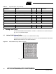
AT91CAP9S500A/AT91CAP9S250A 4.2 400-ball BGA Package Pinout Table 4-1.
Table 4-1.
AT91CAP9S500A/AT91CAP9S250A Table 4-1.
• VDDIOMPA pins: Power the MP Block I/O A lines; voltage ranges from 1.65V to 3.6V, 1.8V, 2.5V, 3V or 3.3V nominal. • VDDIOMPB pins: Power the dedicated MP Block I/O B lines; voltage ranges from 1.65V to 3.6V, 1.8V, 2.5V, 3V or 3.3V nominal. • VDDBU pin: Powers the Slow Clock oscillator and a part of the System Controller; voltage range between1.08V and 1.32V, 1.2V nominal. • VDDPLL pin: Powers the PLL cells; voltage ranges between 3.0V to 3.6V, 3.3V nominal.
AT91CAP9S500A/AT91CAP9S250A 6. I/O Line Considerations 6.1 JTAG Port Pins TMS, TDI and TCK are Schmitt trigger inputs and have no pull-up resistors. TDO and RTCK are outputs, driven at up to VDDIOP0, and have no pull-up resistors. The JTAGSEL pin is used to select the JTAG boundary scan when asserted at a high level. It integrates a permanent pull-down resistor of about 15 kΩ to GNDBU so that it can be left unconnected for normal operations. The NTRST signal is described in Section 6.
7. Processor and Architecture 7.
AT91CAP9S500A/AT91CAP9S250A – Round-Robin Arbitration, either with no default master, last accessed default master or fixed default master • Burst Management – Breaking with Slot Cycle Limit Support – Undefined Burst Length Support • One Address Decoder provided per Master – Three different slaves may be assigned to each decoded memory area: one for internal boot, one for external boot, one after remap • Boot Mode Select – Non-volatile Boot Memory can be internal or external – Selection is made by BMS pin s
The LCD Controller, the DMA Controller, the USB Host and the USB OTG have a user interface mapped as a Slave of the Matrix. They share the same layer, as programming them does not require a high bandwidth. Table 7-2. List of Bus Matrix Slaves Slave 0 Internal SRAM 32 Kbytes Slave 1 MP Block Slave 0 (MP Block Internal Memories) Internal ROM LCD Controller User Interface Slave 2 DMA Controller User Interface USB High Speed Device Interface OHCI USB Host Interface 7.
AT91CAP9S500A/AT91CAP9S250A Table 7-3.
7.6 Peripheral DMA Controller • Acting as one Matrix Master • Allows data transfers from/to peripheral to/from any memory space without any intervention of the processor. • Next Pointer Support, forbids strong real-time constraints on buffer management.
AT91CAP9S500A/AT91CAP9S250A • Embeds 4 unidirectional channels with programmable priority • Address Generation – Source / destination address programming – Address increment, decrement or no change – DMA chaining support for multiple non-contiguous data blocks through use of linked lists – Scatter support for placing fields into a system memory area from a contiguous transfer.
8. Memories Figure 8-1.
AT91CAP9S500A/AT91CAP9S250A A first level of address decoding is performed by the Bus Matrix, i.e., the implementation of the Advanced High-performance Bus (AHB) for its Master and Slave interfaces with additional features. Decoding breaks up the 4G bytes of address space into 16 banks of 256M bytes. The banks 1 to 7 are directed to the EBI that associates these banks to the external chip selects EBI_NCS0 to EBI_NCS5 and EBI_SDDRCS.
Table 8-1. Internal Memory Mapping (Continued) 0x0050 0000 LCD Controller User Interface 0x0060 0000 USB High Speed Device Interface 0x0070 0000 OHCI USB Host User Interface 0x0080 0000 MP Block Slave 1 (hsel[0]) 0x0090 0000 MP Block Slave 1 (hsel[1]) 0x00A0 0000 MP Block Slave 1 (hsel[2]) 0x00B0 0000 MP Block Slave 1 (hsel[3]) 8.1.1.1 Internal 32 Kbyte Fast SRAM The AT91CAP9S500A/AT91CAP9S250A integrates a 32 Kbyte SRAM, mapped at address 0x0010 0000,which is accessible from the AHB bus.
AT91CAP9S500A/AT91CAP9S250A 8.2.1 External Bus Interface The AT91CAP9S500A/AT91CAP9S250A features one External Bus Interface to offer high bandwidth to the system and to prevent any bottleneck while accessing the external memories.
– SDRAM with 16- or 32-bit Data Path – Mobile DDR with four Internal Banks – Mobile DDR with 16-bit Data Path • Programming facilities – Word, half-word, byte access – Automatic page break when Memory Boundary has been reached – Multibank Ping-pong Access – Timing parameters specified by software – Automatic refresh operation, refresh rate is programmable – Multiport (4 Ports) • Energy-saving capabilities – Self-refresh, power down and deep power down modes supported • Error detection – Refresh Error Interr
AT91CAP9S500A/AT91CAP9S250A 8.2.5 Error Corrected Code Controller • Tracking the accesses to a NAND Flash device by trigging on the corresponding chip select • Single bit error correction and 2-bit Random detection.
9.1 System Controller Block Diagram Figure 9-1. AT91CAP9S500A/AT91CAP9S250A System Controller Block Diagram System Controller VDDCORE Powered irq0-irq1 fiq nirq nfiq Advanced Interrupt Controller periph_irq[2..
AT91CAP9S500A/AT91CAP9S250A 9.2 Reset Controller • Based on two Power-on-Reset cells – One on VDDBU and one on VDDCORE • Status of the last reset – Either general reset (VDDBU rising), wake-up reset (VDDCORE rising), software reset, user reset or watchdog reset • Controls the internal resets and the NRST pin output – Allows shaping a reset signal for the external devices 9.
9.
AT91CAP9S500A/AT91CAP9S250A 9.7 Watchdog Timer • 16-bit key-protected only-once-Programmable Counter • Windowed, prevents the processor to be in a dead-lock on the watchdog access 9.8 Real-time Timer • Two Real-time Timers, allowing backup of time with different accuracies – 32-bit Free-running back-up Counter – Integrates a 16-bit programmable prescaler running on the embedded 32,768 Hz oscillator – Alarm Register to generate a wake-up of the system through the Shutdown Controller 9.
• Two-pin UART – Implemented features are 100% compatible with the standard Atmel USART – Independent receiver and transmitter with a common programmable Baud Rate Generator – Even, Odd, Mark or Space Parity Generation – Parity, Framing and Overrun Error Detection – Automatic Echo, Local Loopback and Remote Loopback Channel Modes – Support for two PDC channels with connection to receiver and transmitter • Debug Communication Channel Support – Offers visibility of and interrupt trigger from COMMRX and COMMTX
AT91CAP9S500A/AT91CAP9S250A 10. Peripherals 10.1 User Interface The peripherals are mapped in the upper 256 Mbytes of the address space between the addresses 0xFFFA 0000 and 0xFFFC FFFF. Each user peripheral is allocated 16 Kbytes of address space. A complete memory map is presented in Figure 8-1 on page 22. 10.2 Identifiers The AT91CAP9S500A/AT91CAP9S250A embeds a wide range of peripherals. Table 10-1 defines the Peripheral Identifiers of the AT91CAP9S500A/AT91CAP9S250A.
Table 10-1. 10.2.1 10.2.1.
AT91CAP9S500A/AT91CAP9S250A 10.3 Peripherals Signals Multiplexing on I/O Lines The AT91CAP9S500A/AT91CAP9S250A features 4 PIO controllers, PIOA, PIOB, PIOC and PIOD, that multiplex the I/O lines of the peripheral set. Each PIO Controller controls up to 32 lines. Each line can be assigned to one of two peripheral functions, A or B. The multiplexing tables in the following paragraphs define how the I/O lines of the peripherals A and B are multiplexed on the PIO Controllers.
10.3.1 PIO Controller A Multiplexing Table 10-2.
AT91CAP9S500A/AT91CAP9S250A 10.3.2 PIO Controller B Multiplexing Table 10-3.
10.3.3 PIO Controller C Multiplexing Table 10-4.
AT91CAP9S500A/AT91CAP9S250A 10.3.4 PIO Controller D Multiplexing Table 10-5.
10.4 10.4.
AT91CAP9S500A/AT91CAP9S250A • IrDA modulation and demodulation – Communication at up to 115.2 Kbps • Test Modes – Remote Loopback, Local Loopback, Automatic Echo 10.4.4 Synchronous Serial Controller • Provides serial synchronous communication links used in audio and telecom applications (with CODECs in Master or Slave Modes, I2S, TDM Buses, Magnetic Card Reader, etc.
10.4.
AT91CAP9S500A/AT91CAP9S250A 10.4.10 USB Host Port • Compliance with OHCI Rev 1.0 Specification • Compliance with USB V2.0 Full-speed and Low-speed Specification • Supports both Low-speed 1.5 Mbps and Full-speed 12 Mbps devices • Root hub integrated with two downstream USB ports • Two embedded USB transceivers • Supports power management • Operates as a master on the Matrix • Internal DMA Controller, operating as a Master on Bus Matrix 10.4.11 USB High Speed Device Port • USB V2.
• Full- and half-duplex operations • MII or RMII interface to the physical layer • Register Interface to address, data, status and control registers • Internal DMA Controller, operating as a Master on Bus Matrix • Interrupt generation to signal receive and transmit completion • 28-byte transmit and 28-byte receive FIFOs • Automatic pad and CRC generation on transmitted frames • Address checking logic to recognize four 48-bit addresses • Support promiscuous mode where all valid frames are copied to memory •
AT91CAP9S500A/AT91CAP9S250A 11. Metal Programmable Block The Metal Programmable Block (MPBlock) is connected to internal resources as the AHB bus or interrupts and to external resources as dedicated I/O pads or UTMI+ core. The MPBlock may be used to implement the Advanced High-speed Bus (AHB) or Advanced Peripheral Bus (APB) custom peripherals. The MPBlock adds approximately 500K or 250K gates of standard cell custom logic to the AT91CAP9S500A/AT91CAP9S250A base design.
• 30 or 60 MHz UTMI+ USB Clock • MCK System Clock • DDRCK Dual Rate System Clock • PCK Processor Clock • 5 Gated Peripherals Clock (for AHB and/or APB peripherals) corresponding to Peripheral ID 3 to 7 11.1.2 AHB Master Buses The MPBlock may implement up to three AHB masters, each having a dedicated AHB master bus connected to the Bus Matrix. 11.1.3 AHB Slave Buses The MPBlock receives four different AHB slave buses coming from the Bus Matrix.
AT91CAP9S500A/AT91CAP9S250A 11.2 External Connectivity The MPBlock is connected to the following external resources. 11.2.
AT91CAP9S500A/AT91CAP9S250A Figure 11-2.
AT91CAP9S500A/AT91CAP9S250A 12. ARM926EJ-S Processor Overview 12.1 Overview The ARM926EJ-S processor is a member of the ARM9™ family of general-purpose microprocessors. The ARM926EJ-S implements ARM architecture version 5TEJ and is targeted at multitasking applications where full memory management, high performance, low die size and low power are all important features.
12.2 Block Diagram Figure 12-1. ARM926EJ-S Internal Functional Block Diagram ARM926EJ-S TCM Interface Coprocessor Interface ETM Interface DEXT Droute Data AHB Interface AHB DCACHE WDATA Bus Interface Unit RDATA ARM9EJ-S DA MMU EmbeddedICE -RT Processor Instruction AHB Interface IA AHB INSTR ICE Interface ICACHE Iroute IEXT 12.3 12.3.
AT91CAP9S500A/AT91CAP9S250A • ARM state and Jazelle state using the BXJ instruction All exceptions are entered, handled and exited in ARM state. If an exception occurs in Thumb or Jazelle states, the processor reverts to ARM state. The transition back to Thumb or Jazelle states occurs automatically on return from the exception handler. 12.3.3 Instruction Pipelines The ARM9EJ-S core uses two kinds of pipelines to increase the speed of the flow of instructions to the processor.
• Supervisor mode is a protected mode for the operating system • Abort mode is entered after a data or instruction prefetch abort • System mode is a privileged user mode for the operating system • Undefined mode is entered when an undefined instruction exception occurs Mode changes may be made under software control, or may be brought about by external interrupts or exception processing. Most application programs execute in User Mode.
AT91CAP9S500A/AT91CAP9S250A registers used to hold either data or address values. Register r14 is used as a Link register that holds a value (return address) of r15 when BL or BLX is executed. Register r15 is used as a program counter (PC), whereas the Current Program Status Register (CPSR) contains condition code flags and the current mode bits.
Figure 12-2.
AT91CAP9S500A/AT91CAP9S250A The BKPT, or Undefined instruction, and SWI exceptions are mutually exclusive. There is one exception in the priority scheme though, when FIQs are enabled and a Data Abort occurs at the same time as an FIQ, the ARM9EJ-S core enters the Data Abort handler, and proceeds immediately to FIQ vector. A normal return from the FIQ causes the Data Abort handler to resume execution. Data Aborts must have higher priority than FIQs to ensure that the transfer error does not escape detection.
• Data processing instructions • Status register transfer instructions • Load and Store instructions • Coprocessor instructions • Exception-generating instructions ARM instructions can be executed conditionally. Every instruction contains a 4-bit condition code field (bits[31:28]). Table 12-2 gives the ARM instruction mnemonic list. Table 12-2.
AT91CAP9S500A/AT91CAP9S250A 12.3.9 New ARM Instruction Set . Table 12-3.
Table 12-4. 12.
AT91CAP9S500A/AT91CAP9S250A Table 12-5. Register Name Read/Write (2) 9 cache lockdown Read/write 9 TCM region Read/write 10 TLB lockdown Read/write 11 Reserved None 12 Reserved 13 Notes: CP15 Registers FCSE PID None (1) Read/write (1) 13 Context ID Read/Write 14 Reserved None 15 Test configuration Read/Write 1. Register locations 0,5, and 13 each provide access to more than one register. The register accessed depends on the value of the opcode_2 field. 2.
12.4.1 CP15 Registers Access CP15 registers can only be accessed in privileged mode by: • MCR (Move to Coprocessor from ARM Register) instruction is used to write an ARM register to CP15. • MRC (Move to ARM Register from Coprocessor) instruction is used to read the value of CP15 to an ARM register. Other instructions like CDP, LDC, STC can cause an undefined instruction exception. The assembler code for these instructions is: MCR/MRC{cond} p15, opcode_1, Rd, CRn, CRm, opcode_2.
AT91CAP9S500A/AT91CAP9S250A 12.5 Memory Management Unit (MMU) The ARM926EJ-S processor implements an enhanced ARM architecture v5 MMU to provide virtual memory features required by operating systems like Symbian® OS, Windows CE®, and Linux®. These virtual memory features are memory access permission controls and virtual to physical address translations.
12.5.2 Translation Look-aside Buffer (TLB) The Translation Look-aside Buffer (TLB) caches translated entries and thus avoids going through the translation process every time. When the TLB contains an entry for the MVA (Modified Virtual Address), the access control logic determines if the access is permitted and outputs the appropriate physical address corresponding to the MVA. If access is not permitted, the MMU signals the CPU core to abort.
AT91CAP9S500A/AT91CAP9S250A A new feature is now supported by ARM926EJ-S caches called allocate on read-miss commonly known as wrapping. This feature enables the caches to perform critical word first cache refilling. This means that when a request for a word causes a read-miss, the cache performs an AHB access.
The DCache contains an eight data word entry, single address entry write-back buffer used to hold write-back data for cache line eviction or cleaning of dirty cache lines. The Write Buffer can hold up to 16 words of data and four separate addresses. DCache and Write Buffer operations are closely connected as their configuration is set in each section by the page descriptor in the MMU translation table. 12.6.2.
AT91CAP9S500A/AT91CAP9S250A 12.7.2 Enabling and Disabling TCMs Prior to any enabling step, the user should configure the TCM sizes in HMATRIX TCM register. Then enabling TCMs is performed by using TCM region register (register 9) in CP15. The user should use the same sizes as those put in HMATRIX TCM register. For further details and programming tips, please refer to chapter 2.3 in ARM926EJ-S TRM, ref. DDI0222B. 12.7.
Table 8 gives an overview of the supported transfers and different kinds of transactions they are used for. Table 12-7. HBurst[2:0] Supported Transfers Description Single transfer of word, half word, or byte: • data write (NCNB, NCB, WT, or WB that has missed in DCache) SINGLE Single transfer • data read (NCNB or NCB) • NC instruction fetch (prefetched and non-prefetched) • page table walk read INCR4 Four-word incrementing burst Half-line cache write-back, Instruction prefetch, if enabled.
AT91CAP9S500A/AT91CAP9S250A 13. Debug and Test 13.1 Description The AT91CAP9 features a number of complementary debug and test capabilities. A common JTAG/ICE (In-Circuit Emulator) port is used for standard debugging functions, such as downloading code and single-stepping through programs. The Debug Unit provides a two-pin UART that can be used to upload an application into internal SRAM.
13.2 Block Diagram Figure 13-1.
AT91CAP9S500A/AT91CAP9S250A 13.3 13.3.1 Application Examples Debug Environment Figure 13-2 on page 69 shows a complete debug environment example. The ICE/JTAG interface is used for standard debugging functions, such as downloading code and single-stepping through the program. Figure 13-2. Application Debug and Trace Environment Example Host Debugger ICE/JTAG Interface ICE/JTAG Connector RS232 Connector AT91CAP9 Terminal AT91CAP9-based Application 13.3.
AT91CAP9S500A/AT91CAP9S250A 13.4 Debug and Test Pin Description Table 13-1. Pin Name Debug and Test Pin List Function Type Active Level Input/Output Low Input High Reset/Test NRST Microcontroller Reset TST Test Mode Select ICE and JTAG TCK Test Clock Input TDI Test Data In Input TDO Test Data Out TMS Test Mode Select RTCK Returned Test Clock NTRST Test Reset Input JTAGSEL JTAG Selection Input Output Input Output Low Debug Unit 13.5 13.5.
AT91CAP9S500A/AT91CAP9S250A ARM9EJ-S Technical Reference Manual (DDI 0222A). 13.5.3 JTAG Signal Description • TMS is the Test Mode Select input which controls the transitions of the test interface state machine. • TDI is the Test Data Input line which supplies the data to the JTAG registers (Boundary Scan Register, Instruction Register, or other data registers). • TDO is the Test Data Output line which is used to serially output the data from the JTAG registers to the equipment controlling the test.
AT91CAP9S500A/AT91CAP9S250A It is not possible to switch directly between JTAG and ICE operations. A chip reset must be performed after JTAGSEL is changed. A Boundary-scan Descriptor Language (BSDL) file is provided to set up test. 13.5.
AT91CAP9S500A/AT91CAP9S250A 14. Boot Program 14.1 Description The Boot Program integrates different programs that manage download and/or upload into the different memories of the product. First, it initializes the Debug Unit serial port (DBGU) and the USB Device Port. Then the DataFlash Boot program is executed. It looks for a sequence of seven valid ARM exception vectors in a DataFlash connected to the SPI. All these vectors must be B-branch or LDR load register instructions except for the sixth vector.
Figure 14-1. Boot Program Algorithm Flow Diagram Device Setup SPI DataFlash Boot No Download from DataFlash (NPCS0) Run DataFlash Boot Yes Download from NandFlash Run NandFlash Boot Timeout < 1 s NandFlash Boot No Yes Timeout 1 s Typ.
AT91CAP9S500A/AT91CAP9S250A 14.3 Device Initialization Initialization follows the steps described below: 1. Stack setup for ARM supervisor mode 2. Main Oscillator Frequency Detection 3. C variable initialization 4. PLL setup: PLLB is initialized to generate a 48 MHz clock necessary to use the USB Device. A register located in the Power Management Controller (PMC) determines the frequency of the main oscillator and thus the correct factor for the PLLB.
AT91CAP9S500A/AT91CAP9S250A 14.4 DataFlash Boot The DataFlash Boot program searches for a valid application in the SPI DataFlash memory. If a valid application is found, this application is loaded into internal SRAM and executed by branching at address 0x0000_0000 after remap. This application may be the application code or a second-level bootloader. All the calls to functions are PC relative and do not use absolute addresses.
AT91CAP9S500A/AT91CAP9S250A Figure 14-5. Structure of the ARM Vector 6 31 0 Size of the code to download in bytes 14.4.2.1 Example An example of valid vectors follows: 00 ea000006 B 0x20 04 eafffffe B 0x04 08 ea00002f B _main 0c eafffffe B 0x0c 10 eafffffe B 0x10 14 00001234 B 0x14 18 eafffffe B 0x18 <- Code size = 4660 bytes The size of the image to load into SRAM is contained in the location of the sixth ARM vector.
AT91CAP9S500A/AT91CAP9S250A Figure 14-6. Serial DataFlash Download Start Send status command Is status OK ? No Jump to next boot solution Yes Read the first 7 instructions (28 bytes). Decode the sixth ARM vector 7 vectors (except vector 6) are LDR or Branch instruction No Yes Read the DataFlash into the internal SRAM. (code size to read in vector 6) Restore the reset value for the peripherals. Set the PC to 0 and perform the REMAP to jump to the downloaded application End 14.
AT91CAP9S500A/AT91CAP9S250A 14.5.1 Supported NANDFlash Devices Any 8 or 16-bit NANDFlash Devices from 1 Mbit to 16 Gbit density. Table 14-3. Supported NANDFlash Manufacturers Manufacturer Identifier ® 0x98 Toshiba Samsung ® 0xEC Fujitsu 0x04 National Semiconductor® 0x8F Renesas 0x07 STMicroelectronics 0x20 ® 0x2C Micron 14.6 SAM-BA Boot If no valid DataFlash device has been found during the DataFlash boot sequence, the SAMBA boot program is performed.
AT91CAP9S500A/AT91CAP9S250A – Output: The byte, halfword or word read in hexadecimal following by ‘>’ • Send a file (S): Send a file to a specified address – Address: Address in hexadecimal – Output: ‘>’. Note: There is a time-out on this command which is reached when the prompt ‘>’ appears before the end of the command execution.
AT91CAP9S500A/AT91CAP9S250A Figure 14-7. Xmodem Transfer Example Host Device C SOH 01 FE Data[128] CRC CRC ACK SOH 02 FD Data[128] CRC CRC ACK SOH 03 FC Data[100] CRC CRC ACK EOT ACK 14.6.3 USB Device Port A 48 MHz USB clock is necessary to use the USB Device port. It has been programmed earlier in the device initialization procedure with PLLB configuration. The device uses the USB communication device class (CDC) drivers to take advantage of the installed PC RS-232 software to talk over the USB.
AT91CAP9S500A/AT91CAP9S250A The device also handles some class requests defined in the CDC class. Table 14-6. Handled Class Requests Request Definition SET_LINE_CODING Configures DTE rate, stop bits, parity and number of character bits. GET_LINE_CODING Requests current DTE rate, stop bits, parity and number of character bits. SET_CONTROL_LINE_STATE RS-232 signal used to tell the DCE device the DTE device is now present. Unhandled requests are STALLed. 14.6.3.
AT91CAP9S500A/AT91CAP9S250A Before performing the jump to the application in internal SRAM, all the PIOs and peripherals used in the boot program are set to their reset state. Table 14-7.
AT91CAP9S500A/AT91CAP9S250A 6264A–CAP–21-May-07
AT91CAP9S500A/AT91CAP9S250A 15. Reset Controller (RSTC) 15.1 Description The Reset Controller (RSTC), based on power-on reset cells, handles all the resets of the system without any external components. It reports which reset occurred last. The Reset Controller also drives independently or simultaneously the external reset and the peripheral and processor resets. 15.2 Block Diagram Figure 15-1.
The startup counter waits for the complete crystal oscillator startup. The wait delay is given by the crystal oscillator startup time maximum value that can be found in the section Crystal Oscillator Characteristics in the Electrical Characteristics section of the product documentation. The Reset Controller Mode Register (RSTC_MR), allowing the configuration of the Reset Controller, is powered with VDDBU, so that its configuration is saved as long as VDDBU is on. 15.3.
AT91CAP9S500A/AT91CAP9S250A As the field is within RSTC_MR, which is backed-up, this field can be used to shape the system power-up reset for devices requiring a longer startup time than the Slow Clock Oscillator. 15.3.3 BMS Sampling The product matrix manages a boot memory that depends on the level on the BMS pin at reset. The BMS signal is sampled three slow clock cycles after the Core Power-On-Reset output rising edge. Figure 15-3.
Figure 15-4. General Reset State SLCK Any Freq.
AT91CAP9S500A/AT91CAP9S250A 15.3.4.2 Wake-up Reset The Wake-up Reset occurs when the Main Supply is down. When the Main Supply POR output is active, all the reset signals are asserted except backup_nreset. When the Main Supply powers up, the POR output is resynchronized on Slow Clock. The processor clock is then re-enabled during Y Slow Clock cycles, depending on the requirements of the ARM processor. At the end of this delay, the processor and other reset signals rise.
15.3.4.3 User Reset The User Reset is entered when a low level is detected on the NRST pin and the bit URSTEN in RSTC_MR is at 1. The NRST input signal is resynchronized with SLCK to insure proper behavior of the system. The User Reset is entered as soon as a low level is detected on NRST. The Processor Reset and the Peripheral Reset are asserted. The User Reset is left when NRST rises, after a two-cycle resynchronization time and a Y-cycle processor startup.
AT91CAP9S500A/AT91CAP9S250A 15.3.4.4 Software Reset The Reset Controller offers several commands used to assert the different reset signals. These commands are performed by writing the Control Register (RSTC_CR) with the following bits at 1: • PROCRST: Writing PROCRST at 1 resets the processor and the watchdog timer. • PERRST: Writing PERRST at 1 resets all the embedded peripherals, including the memory system, and, in particular, the Remap Command.
Figure 15-7. Software Reset SLCK MCK Any Freq. Write RSTC_CR Resynch.
AT91CAP9S500A/AT91CAP9S250A 15.3.4.5 Watchdog Reset The Watchdog Reset is entered when a watchdog fault occurs. This state lasts Y Slow Clock cycles. When in Watchdog Reset, assertion of the reset signals depends on the WDRPROC bit in WDT_MR: • If WDRPROC is 0, the Processor Reset and the Peripheral Reset are asserted. The NRST line is also asserted, depending on the programming of the field ERSTL. However, the resulting low level on NRST does not result in a User Reset state.
• When in User Reset: – A watchdog event is impossible because the Watchdog Timer is being reset by the proc_nreset signal. – A software reset is impossible, since the processor reset is being activated. • When in Software Reset: – A watchdog event has priority over the current state. – The NRST has no effect. • When in Watchdog Reset: – The processor reset is active and so a Software Reset cannot be programmed. – A User Reset cannot be entered. 15.3.
AT91CAP9S500A/AT91CAP9S250A 15.4 Reset Controller (RSTC) User Interface Table 15-1. Reset Controller (RSTC) Register Mapping Offset Register Name 0x00 Control Register 0x04 0x08 Note: Back-up Reset Value Access Reset Value RSTC_CR Write-only - Status Register RSTC_SR Read-only 0x0000_0001 0x0000_0000 Mode Register RSTC_MR Read/Write - 0x0000_0000 1. The reset value of RSTC_SR either reports a General Reset or a Wake-up Reset depending on last rising power supply.
15.4.1 Reset Controller Control Register Register Name: RSTC_CR Access Type: 31 Write-only 30 29 28 27 26 25 24 KEY 23 – 22 – 21 – 20 – 19 – 18 – 17 – 16 – 15 – 14 – 13 – 12 – 11 – 10 – 9 8 – 7 – 6 – 5 – 4 – 3 EXTRST 2 PERRST 1 – 0 PROCRST • PROCRST: Processor Reset 0 = No effect. 1 = If KEY is correct, resets the processor. • PERRST: Peripheral Reset 0 = No effect. 1 = If KEY is correct, resets the peripherals. • EXTRST: External Reset 0 = No effect.
AT91CAP9S500A/AT91CAP9S250A 15.4.2 Reset Controller Status Register Register Name: RSTC_SR Access Type: Read-only 31 – 30 – 29 – 28 – 27 – 26 – 25 – 24 – 23 – 22 – 21 – 20 – 19 – 18 – 17 SRCMP 16 NRSTL 15 – 14 – 13 – 12 – 11 – 10 9 RSTTYP 8 7 – 6 – 5 – 4 – 3 – 2 – 1 – 0 URSTS • URSTS: User Reset Status 0 = No high-to-low edge on NRST happened since the last read of RSTC_SR. 1 = At least one high-to-low transition of NRST has been detected since the last read of RSTC_SR.
15.4.3 Reset Controller Mode Register Register Name: RSTC_MR Access Type: 31 Read/Write 30 29 28 27 26 25 24 KEY 23 – 22 – 21 – 20 – 19 – 18 – 17 – 16 15 – 14 – 13 – 12 – 11 10 9 8 7 – 6 – 5 4 URSTIEN 3 – 1 – 0 URSTEN ERSTL 2 – • URSTEN: User Reset Enable 0 = The detection of a low level on the pin NRST does not generate a User Reset. 1 = The detection of a low level on the pin NRST triggers a User Reset.
AT91CAP9S500A/AT91CAP9S250A 16. Real-time Timer (RTT) 16.1 Overview The Real-time Timer is built around a 32-bit counter and used to count elapsed seconds. It generates a periodic interrupt and/or triggers an alarm on a programmed value. 16.2 Block Diagram Figure 16-1.
The Real-time Timer value (CRTV) can be read at any time in the register RTT_VR (Real-time Value Register). As this value can be updated asynchronously from the Master Clock, it is advisable to read this register twice at the same value to improve accuracy of the returned value. The current value of the counter is compared with the value written in the alarm register RTT_AR (Real-time Alarm Register). If the counter value matches the alarm, the bit ALMS in RTT_SR is set.
AT91CAP9S500A/AT91CAP9S250A 16.4 Real-time Timer (RTT) User Interface Table 16-1.
16.4.1 Real-time Timer Mode Register Register Name: RTT_MR Access Type: Read/Write 31 – 30 – 29 – 28 – 27 – 26 – 25 – 24 – 23 – 22 – 21 – 20 – 19 – 18 RTTRST 17 RTTINCIEN 16 ALMIEN 15 14 13 12 11 10 9 8 3 2 1 0 RTPRES 7 6 5 4 RTPRES • RTPRES: Real-time Timer Prescaler Value Defines the number of SLCK periods required to increment the Real-time timer.
AT91CAP9S500A/AT91CAP9S250A 16.4.2 Real-time Timer Alarm Register Register Name: RTT_AR Access Type: Read/Write 31 30 29 28 27 26 25 24 19 18 17 16 11 10 9 8 3 2 1 0 27 26 25 24 19 18 17 16 11 10 9 8 3 2 1 0 ALMV 23 22 21 20 ALMV 15 14 13 12 ALMV 7 6 5 4 ALMV • ALMV: Alarm Value Defines the alarm value (ALMV+1) compared with the Real-time Timer. 16.4.
16.4.4 Real-time Timer Status Register Register Name: RTT_SR Access Type: Read-only 31 – 30 – 29 – 28 – 27 – 26 – 25 – 24 – 23 – 22 – 21 – 20 – 19 – 18 – 17 – 16 – 15 – 14 – 13 – 12 – 11 – 10 – 9 – 8 – 7 – 6 – 5 – 4 – 3 – 2 – 1 RTTINC 0 ALMS • ALMS: Real-time Alarm Status 0 = The Real-time Alarm has not occured since the last read of RTT_SR. 1 = The Real-time Alarm occured since the last read of RTT_SR.
AT91CAP9S500A/AT91CAP9S250A 17. Periodic Interval Timer (PIT) 17.1 Overview The Periodic Interval Timer (PIT) provides the operating system’s scheduler interrupt. It is designed to offer maximum accuracy and efficient management, even for systems with long response time. 17.2 Block Diagram Figure 17-1.
17.3 Functional Description The Periodic Interval Timer aims at providing periodic interrupts for use by operating systems. The PIT provides a programmable overflow counter and a reset-on-read feature. It is built around two counters: a 20-bit CPIV counter and a 12-bit PICNT counter. Both counters work at Master Clock /16. The first 20-bit CPIV counter increments from 0 up to a programmable overflow value set in the field PIV of the Mode Register (PIT_MR).
AT91CAP9S500A/AT91CAP9S250A Figure 17-2.
17.4 Periodic Interval Timer (PIT) User Interface Table 17-1.
AT91CAP9S500A/AT91CAP9S250A 17.4.1 Periodic Interval Timer Mode Register Register Name: PIT_MR Access Type: Read/Write 31 – 30 – 29 – 28 – 27 – 26 – 25 PITIEN 24 PITEN 23 – 22 – 21 – 20 – 19 18 17 16 15 14 13 12 PIV 11 10 9 8 3 2 1 0 PIV 7 6 5 4 PIV • PIV: Periodic Interval Value Defines the value compared with the primary 20-bit counter of the Periodic Interval Timer (CPIV). The period is equal to (PIV + 1).
17.4.2 Periodic Interval Timer Status Register Register Name: PIT_SR Access Type: Read-only 31 – 30 – 29 – 28 – 27 – 26 – 25 – 24 – 23 – 22 – 21 – 20 – 19 – 18 – 17 – 16 – 15 – 14 – 13 – 12 – 11 – 10 – 9 – 8 – 7 – 6 – 5 – 4 – 3 – 2 – 1 – 0 PITS • PITS: Periodic Interval Timer Status 0 = The Periodic Interval timer has not reached PIV since the last read of PIT_PIVR. 1 = The Periodic Interval timer has reached PIV since the last read of PIT_PIVR. 17.4.
AT91CAP9S500A/AT91CAP9S250A 17.4.4 Periodic Interval Timer Image Register Register Name: PIT_PIIR Access Type: Read-only 31 30 29 28 27 26 25 24 19 18 17 16 PICNT 23 22 21 20 PICNT 15 14 CPIV 13 12 11 10 9 8 3 2 1 0 CPIV 7 6 5 4 CPIV • CPIV: Current Periodic Interval Value Returns the current value of the periodic interval timer. • PICNT: Periodic Interval Counter Returns the number of occurrences of periodic intervals since the last read of PIT_PIVR.
AT91CAP9S500A/AT91CAP9S250A 6264A–CAP–21-May-07
AT91CAP9S500A/AT91CAP9S250A 18. Watchdog Timer (WDT) 18.1 Description The Watchdog Timer can be used to prevent system lock-up if the software becomes trapped in a deadlock. It features a 12-bit down counter that allows a watchdog period of up to 16 seconds (slow clock at 32.768 kHz). It can generate a general reset or a processor reset only. In addition, it can be stopped while the processor is in debug mode or idle mode. 18.2 Block Diagram Figure 18-1.
18.3 Functional Description The Watchdog Timer can be used to prevent system lock-up if the software becomes trapped in a deadlock. It is supplied with VDDCORE. It restarts with initial values on processor reset. The Watchdog is built around a 12-bit down counter, which is loaded with the value defined in the field WDV of the Mode Register (WDT_MR). The Watchdog Timer uses the Slow Clock divided by 128 to establish the maximum Watchdog period to be 16 seconds (with a typical Slow Clock of 32.768 kHz).
Figure 18-2.
18.4 Watchdog Timer (WDT) User Interface Table 18-1.
18.4.1 Watchdog Timer Control Register Register Name: WDT_CR Access Type: 31 Write-only 30 29 28 27 26 25 24 KEY 23 – 22 – 21 – 20 – 19 – 18 – 17 – 16 – 15 – 14 – 13 – 12 – 11 – 10 – 9 – 8 – 7 – 6 – 5 – 4 – 3 – 2 – 1 – 0 WDRSTT • WDRSTT: Watchdog Restart 0: No effect. 1: Restarts the Watchdog. • KEY: Password Should be written at value 0xA5. Writing any other value in this field aborts the write operation.
18.4.2 Watchdog Timer Mode Register Register Name: WDT_MR Access Type: 31 Read/Write Once 30 23 29 WDIDLEHLT 28 WDDBGHLT 27 21 20 19 11 22 26 25 24 18 17 16 10 9 8 1 0 WDD WDD 15 WDDIS 14 13 12 WDRPROC WDRSTEN WDFIEN 7 6 5 4 WDV 3 2 WDV • WDV: Watchdog Counter Value Defines the value loaded in the 12-bit Watchdog Counter. • WDFIEN: Watchdog Fault Interrupt Enable 0: A Watchdog fault (underflow or error) has no effect on interrupt.
18.4.3 Watchdog Timer Status Register Register Name: WDT_SR Access Type: Read-only 31 – 30 – 29 – 28 – 27 – 26 – 25 – 24 – 23 – 22 – 21 – 20 – 19 – 18 – 17 – 16 – 15 – 14 – 13 – 12 – 11 – 10 – 9 – 8 – 7 – 6 – 5 – 4 – 3 – 2 – 1 WDERR 0 WDUNF • WDUNF: Watchdog Underflow 0: No Watchdog underflow occurred since the last read of WDT_SR. 1: At least one Watchdog underflow occurred since the last read of WDT_SR.
AT91CAP9S500A/AT91CAP9S250A 6264A–CAP–21-May-07
AT91CAP9S500A/AT91CAP9S250A 19. Shutdown Controller (SHDWC) 19.1 Description The Shutdown Controller controls the power supplies VDDIO and VDDCORE and the wake-up detection on debounced input lines. 19.2 Block Diagram Figure 19-1.
A typical application connects the pin SHDN to the shutdown input of the DC/DC Converter providing the main power supplies of the system, and especially VDDCORE and/or VDDIO. The wake-up inputs (WKUP0) connect to any push-buttons or signal that wake up the system. The software is able to control the pin SHDN by writing the Shutdown Control Register (SHDW_CR) with the bit SHDW at 1. The shutdown is taken into account only 2 slow clock cycles after the write of SHDW_CR.
AT91CAP9S500A/AT91CAP9S250A 19.6 Shutdown Controller (SHDWC) User Interface 19.6.1 Register Mapping Table 19-2. Shutdown Controller (SHDWC) Registers Offset Register Name Access Reset Value 0x00 Shutdown Control Register SHDW_CR Write-only - 0x04 Shutdown Mode Register SHDW_MR Read-Write 0x0000 0103 0x08 Shutdown Status Register SHDW_SR Read-only 0x0000_0000 19.6.
19.6.3 Shutdown Mode Register Register Name: SHDW_MR Access Type: Read/Write 31 – 30 – 29 – 28 – 27 – 26 – 25 – 24 – 23 – 22 – 21 – 20 – 19 – 18 – 17 – 16 RTTWKEN 15 14 13 12 11 – 10 – 9 8 3 – 2 – 1 – 7 6 5 4 CPTWK0 – 0 WKMODE0 • WKMODE0: Wake-up Mode 0 WKMODE[1:0] Wake-up Input Transition Selection 0 0 None.
AT91CAP9S500A/AT91CAP9S250A 19.6.4 Shutdown Status Register Register Name: SHDW_SR Access Type: Read-only 31 – 30 – 29 – 28 – 27 – 26 – 25 – 24 – 23 – 22 – 21 – 20 – 19 – 18 – 17 – 16 RTTWK 15 – 14 – 13 – 12 – 11 – 10 – 9 – 8 – 7 – 6 – 5 – 4 – 3 – 2 – 1 – 0 WAKEUP0 • WAKEUP0: Wake-up 0 Status 0 = No wake-up event occurred on the corresponding wake-up input since the last read of SHDW_SR.
AT91CAP9S500A/AT91CAP9S250A 6264A–CAP–21-May-07
AT91CAP9S500A/AT91CAP9S250A 127 6264A–CAP–21-May-07
AT91CAP9S500A/AT91CAP9S250A 6264A–CAP–21-May-07
AT91CAP9S500A/AT91CAP9S250A 20. Bus Matrix 20.1 Description The Bus Matrix implements a multi-layer AHB, based on AHB-Lite protocol, that enables parallel access paths between multiple AHB masters and slaves in a system, which increases the overall bandwidth. Bus Matrix interconnects 12 AHB Masters to 10 AHB Slaves. The normal latency to connect a master to a slave is one cycle except for the default master of the accessed slave which is connected directly (zero cycle latency).
The 2-bit DEFMSTR_TYPE field selects the default master type (no default, last access master, fixed default master) whereas the 4-bit FIXED_DEFMSTR field selects a fixed default master provided that DEFMSTR_TYPE is set to fixed default master. Refer to the Section 20.5, ”Bus Matrix User Interface”, on page 133. 20.
AT91CAP9S500A/AT91CAP9S250A 4. Sixteen beat bursts: predicted end of burst is generated at the end of each sixteen beat boundary inside INCR transfer. This selection can be done through the field ULBT of the Master Configuration Registers (MATRIX_MCFG). 20.4.1.2 20.4.2 Slot Cycle Limit Arbitration The Bus Matrix contains specific logic to break too long accesses such as very long bursts on a very slow slave (e.g. an external low speed memory).
20.4.3 Fixed Priority Arbitration This algorithm allows the Bus Matrix arbiters to dispatch the requests from different masters to the same slave by using the fixed priority defined by the user. If two or more master’s requests are active at the same time, the master with the highest priority number is serviced first. If two or more master’s requests with the same priority are active at the same time, the master with the highest number is serviced first.
AT91CAP9S500A/AT91CAP9S250A 20.5 Bus Matrix User Interface Table 20-1.
AT91CAP9S500A/AT91CAP9S250A Table 20-1.
AT91CAP9S500A/AT91CAP9S250A 20.5.1 Bus Matrix Master Configuration Registers Register Name: MATRIX_MCFG0...
AT91CAP9S500A/AT91CAP9S250A 20.5.2 Bus Matrix Slave Configuration Registers Register Name: MATRIX_SCFG0...
AT91CAP9S500A/AT91CAP9S250A 20.5.3 Bus Matrix Priority Registers A For Slaves Register Name: MATRIX_PRAS0...MATRIX_PRAS9 Access Type: Read/Write 31 30 – – 23 22 – – 15 14 – – 7 6 – – 29 28 M7PR 21 20 M5PR 13 12 M3PR 5 4 M1PR 27 26 – – 19 18 – – 11 10 – – 3 2 – – 25 24 M6PR 17 16 M4PR 9 8 M2PR 1 0 M0PR • MxPR: Master x Priority Fixed prority of Master x for accessing to the selected slave.The higher the number, the higher the priority. 20.5.
AT91CAP9S500A/AT91CAP9S250A 20.5.5 Bus Matrix Master Remap Control Register Register Name: MATRIX_MRCR Access Type: Read/Write Reset: 0x0000_0000 31 30 29 28 27 26 25 24 – – – – – – – – 23 22 21 20 19 18 17 16 – – – – – – – – 15 14 13 12 11 10 9 8 – – – – – – – RCB8 7 6 5 4 3 2 1 0 RCB7 RCB6 RCB5 RCB4 RCB3 RCB2 RCB1 RCB0 • RCBx: Remap Command Bit for AHB Master x 0: Disable remapped address decoding for the selected Master.
AT91CAP9S500A/AT91CAP9S250A 20.6 Chip Configuration User Interface Table 20-2.
AT91CAP9S500A/AT91CAP9S250A MPBS1_SFR 7 6 5 4 3 2 1 0 MPBS1_SFR • MPBS0_SFR: MPBlock Slave 1 Special Function Register The value of the register is directy connected to MPBlock inputs and may be used to implement any MPBlock configuration register 20.6.
AT91CAP9S500A/AT91CAP9S250A 20.6.4 MPBlock Slave 2 Special Function Register Register Name: MPBS2_SFR Access Type: Read/Write Reset: 0x0000_0000 31 30 29 28 27 26 25 24 19 18 17 16 11 10 9 8 3 2 1 0 MPBS2_SFR 23 22 21 20 MPBS2_SFR 15 14 13 12 MPBS2_SFR 7 6 5 4 MPBS2_SFR • MPBS0_SFR: MPBlock Slave 2 Special Function Register The value of the register is directy connected to MPBlock inputs and may be used to implement any MPBlock configuration register 20.6.
20.6.
AT91CAP9S500A/AT91CAP9S250A 21. External Bus Interface (EBI) 21.1 Description The External Bus Interface (EBI) is designed to ensure the successful data transfer between several external devices and the embedded Memory Controller of an ARM-based device. The Static Memory, DDR/SDRAM, Burst CellularRAM and ECC Controllers are all featured external Memory Controllers on the EBI.
Figure 21-1.
AT91CAP9S500A/AT91CAP9S250A 21.2 I/O Lines Description Table 21-1.
AT91CAP9S500A/AT91CAP9S250A Table 21-1.
AT91CAP9S500A/AT91CAP9S250A 21.3 Application Example 21.3.1 Hardware Interface Table 21-2 on page 147 details the connections to be applied between the EBI pins and the external devices for each Memory Controller. Table 21-2.
AT91CAP9S500A/AT91CAP9S250A Table 21-3.
AT91CAP9S500A/AT91CAP9S250A Table 21-3.
AT91CAP9S500A/AT91CAP9S250A 21.5.1 Bus Multiplexing The EBI offers a complete set of control signals that share the 32-bit data lines, the address lines of up to 26 bits and the control signals through a multiplex logic operating in function of the memory area requests. Multiplexing is specifically organized in order to guarantee the maintenance of the address and output control lines at a stable state while no external access is being performed.
AT91CAP9S500A/AT91CAP9S250A 21.5.8.1 I/O Mode, Common Memory Mode, Attribute Memory Mode and True IDE Mode Within the NCS4 and/or NCS5 address space, the current transfer address is used to distinguish I/O mode, common memory mode, attribute memory mode and True IDE mode. The different modes are accessed through a specific memory mapping as illustrated on Figure 21-2. A[23:21] bits of the transfer address are used to select the desired mode as described in Table 21-4 on page 151. Figure 21-2.
AT91CAP9S500A/AT91CAP9S250A The CFCE1 and CFCE2 waveforms are identical to the corresponding NCSx waveform. For details on these waveforms and timings, refer to the section “Static Memory Controller”. Table 21-5.
AT91CAP9S500A/AT91CAP9S250A Figure 21-3. CompactFlash Read/Write Control Signals External Bus Interface SMC CompactFlash Logic A23 1 1 0 1 0 0 CFOE CFWE 1 1 A22 NRD_NOE NWR0_NWE 0 1 1 Table 21-6. CFIOR CFIOW 1 CompactFlash Mode Selection Mode Base Address CFOE CFWE CFIOR CFIOW NRD NWR0_NWE 1 1 I/O Mode 1 1 NRD NWR0_NWE True IDE Mode 0 1 NRD NWR0_NWE Attribute Memory Common Memory 21.5.8.
AT91CAP9S500A/AT91CAP9S250A Table 21-8. Shared CompactFlash Interface Multiplexing Access to CompactFlash Device Access to Other EBI Devices Pins CompactFlash Signals EBI Signals NRD/CFOE CFOE NRD NWR0/NWE/CFWE CFWE NWR0/NWE NWR1/NBS1/CFIOR CFIOR NWR1/NBS1 NWR3/NBS3/CFIOW CFIOW NWR3/NBS3 A25/CFRNW CFRNW A25 21.5.8.5 Application Example Figure 21-4 on page 154 illustrates an example of a CompactFlash application.
AT91CAP9S500A/AT91CAP9S250A 21.5.9 21.5.9.1 NAND Flash Support External Bus Interface integrates circuitry that interfaces to NAND Flash devices. External Bus Interface The NAND Flash logic is driven by the Static Memory Controller on the NCS3 address space. Programming the EBI_CS3A field in the EBI_CSA Register in the Chip Configuration User Interface to the appropriate value enables the NAND Flash logic. For details on this register, refer to Section 20. ”Bus Matrix” on page 129.
AT91CAP9S500A/AT91CAP9S250A Figure 21-6.
AT91CAP9S500A/AT91CAP9S250A 21.6 Implementation Examples 21.6.1 21.6.1.1 16-bit SDRAM Hardware Configuration D[0..15] A[0..17] (Not used A1, A12, A15) U1 A2 A3 A4 A5 A6 A7 A8 A9 A10 A11 23 24 25 26 29 30 31 32 33 34 22 35 A0 A1 A2 A3 A4 A5 A6 A7 A8 A9 A10 A11 A16 A17 20 21 BA0 BA1 A14 36 40 A12 N.C SDCKE 37 CKE SDCK 38 CLK A0 (NBS0) NBS1 15 39 DQML DQMH CAS RAS 17 18 CAS RAS SDWE SDDRCS 16 19 WE CS A13 21.6.1.
21.6.2 21.6.2.1 32-bit SDRAM Hardware Configuration D[0..31] A[0..17] (Not used A12, A15) U1 A2 A3 A4 A5 A6 A7 A8 A9 A10 A11 A13 A16 A17 20 21 A14 36 40 A0 21.6.2.2 SDA10 23 24 25 26 29 30 31 32 33 34 22 35 A0 A1 A2 A3 A4 A5 A6 A7 A8 A9 A10 A11 BA0 BA1 A12 N.
AT91CAP9S500A/AT91CAP9S250A 21.6.3 21.6.3.1 16-bit Mobile DDR Hardware Configuration D[0..15] A[0..17] U1 A2 A3 A4 A5 A6 A7 A8 A9 A10 A11 J8 J9 K7 K8 K2 K3 J1 J2 J3 H1 J7 H2 H3 A0 A1 A2 A3 A4 A5 A6 A7 A8 A9 A10 A11 A12 A16 (BA0) A17 (BA1) H8 H9 BA0 BA1 A0 (NBS0) NBS1 F8 F2 LDM UDM SDCKE SDCK SDCKN G1 G2 G3 CKE CK CK DQS0 DQS1 E8 E2 LDQS UDQS CAS RAS G8 G9 CAS RAS SDWE SDDRCS G7 H7 WE CS F3 F7 N.C N.C A13 A14 21.6.3.
21.6.4 21.6.4.1 16-bit BCRAM Hardware Configuration D[0..15] A[2..
AT91CAP9S500A/AT91CAP9S250A 21.6.5 21.6.5.1 8-bit NAND Flash Hardware Configuration D[0..7] U1 CLE ALE NANDOE NANDWE (ANY PIO) (ANY PIO) R1 3V3 R2 10K 16 17 8 18 9 CLE ALE RE WE CE 7 R/B 19 WP 10K 1 2 3 4 5 6 10 11 14 15 20 21 22 23 24 25 26 K9F2G08U0M N.C N.C N.C N.C N.C N.C N.C N.C N.C N.C N.C N.C N.C N.C N.C N.C N.C I/O0 I/O1 I/O2 I/O3 I/O4 I/O5 I/O6 I/O7 29 30 31 32 41 42 43 44 N.C N.C N.C N.C N.C N.C PRE N.C N.C N.C N.C N.
21.6.6 16-bit NAND Flash 21.6.6.1 Hardware Configuration D[0..15] U1 CLE ALE NANDOE NANDWE (ANY PIO) (ANY PIO) R1 3V3 R2 10K 16 17 8 18 9 CLE ALE RE WE CE 7 R/B 19 WP 1 2 3 4 5 6 10 11 14 15 20 21 22 23 24 34 35 N.C N.C N.C N.C N.C N.C N.C N.C N.C N.C N.C N.C N.C N.C N.C N.C N.C 10K MT29F2G16AABWP-ET I/O0 26 I/O1 28 I/O2 30 I/O3 32 I/O4 40 I/O5 42 I/O6 44 I/O7 46 I/O8 27 I/O9 29 I/O10 31 I/O11 33 I/O12 41 I/O13 43 I/O14 45 I/O15 47 N.C PRE N.
AT91CAP9S500A/AT91CAP9S250A 21.6.7 21.6.7.1 NOR Flash on NCS0 Hardware Configuration D[0..15] A[1..
21.6.8 21.6.8.1 Compact Flash Hardware Configuration MEMORY & I/O MODE D[0..
AT91CAP9S500A/AT91CAP9S250A 21.6.8.2 Software Configuration The following configuration has to be performed: • Assign the EBI CS4 and/or EBI_CS5 to the CompactFlash Slot 0 or/and Slot 1 by setting the bit EBI_CS4A or/and EBI_CS5A in the EBI Chip Select Assignment Register located in the bus matrix memory space. • The address line A23 is to select I/O (A23=1) or Memory mode (A23=0) and the address line A22 for REG function.
21.6.9 21.6.9.1 Compact Flash True IDE Hardware Configuration TRUE IDE MODE D[0..
AT91CAP9S500A/AT91CAP9S250A 21.6.9.2 Software Configuration The following configuration has to be performed: • Assign the EBI CS4 and/or EBI_CS5 to the CompactFlash Slot 0 or/and Slot 1 by setting the bit EBI_CS4A or/and EBI_CS5A in the EBI Chip Select Assignment Register located in the bus matrix memory space. • The address line A21 is to select Alternate True IDE (A21=1) or True IDE (A21=0) modes.
AT91CAP9S500A/AT91CAP9S250A 6264A–CAP–21-May-07
AT91CAP9S500A/AT91CAP9S250A 22. Static Memory Controller (SMC) 22.1 Description The Static Memory Controller (SMC) generates the signals that control the access to the external memory devices or peripheral devices. It has 6 Chip Selects and a 26-bit address bus. The 32-bit data bus can be configured to interface with 8-, 16-, or 32-bit external devices. Separate read and write control signals allow for direct memory and peripheral interfacing. Read and write signal waveforms are fully parametrizable.
22.4 22.4.1 Application Example Hardware Interface Figure 22-1. SMC Connections to Static Memory Devices D0-D31 A0/NBS0 NWR0/NWE NWR1/NBS1 A1/NWR2/NBS2 NWR3/NBS3 D0 - D7 128K x 8 SRAM D8-D15 D0 - D7 CS NRD NWR0/NWE A2 - A25 A2 - A18 A0 - A16 NRD OE NWR1/NBS1 WE 128K x 8 SRAM D16 - D23 D24-D31 D0 - D7 A0 - A16 NRD Static Memory Controller 22.5 22.5.
AT91CAP9S500A/AT91CAP9S250A 22.6 External Memory Mapping The SMC provides up to 26 address lines, A[25:0]. This allows each chip select line to address up to 64 Mbytes of memory. If the physical memory device connected on one chip select is smaller than 64 Mbytes, it wraps around and appears to be repeated within this space. The SMC correctly handles any valid access to the memory device within the page (see Figure 22-2).
Figure 22-3. Memory Connection for an 8-bit Data Bus D[7:0] D[7:0] A[18:2] A[18:2] SMC A0 A0 A1 A1 NWE Write Enable NRD Output Enable NCS[2] Figure 22-4. Memory Enable Memory Connection for a 16-bit Data Bus D[15:0] D[15:0] A[19:2] A[18:1] A1 SMC A[0] NBS0 Low Byte Enable NBS1 High Byte Enable NWE Write Enable NRD Output Enable NCS[2] Memory Enable Figure 22-5.
AT91CAP9S500A/AT91CAP9S250A 22.7.2.1 Byte Write Access Byte write access supports one byte write signal per byte of the data bus and a single read signal. Note that the SMC does not allow boot in Byte Write Access mode. • For 16-bit devices: the SMC provides NWR0 and NWR1 write signals for respectively byte0 (lower byte) and byte1 (upper byte) of a 16-bit bus. One single read signal (NRD) is provided. Byte Write Access is used to connect 2 x 8-bit devices as a 16-bit memory.
Figure 22-6. Connection of 2 x 8-bit Devices on a 16-bit Bus: Byte Write Option D[7:0] D[7:0] D[15:8] A[24:2] SMC A1 NWR0 A[23:1] A[0] Write Enable NWR1 NRD NCS[3] Read Enable Memory Enable D[15:8] A[23:1] A[0] Write Enable Read Enable Memory Enable 22.7.2.3 Signal Multiplexing Depending on the BAT, only the write signals or the byte select signals are used. To save IOs at the external bus interface, control signals at the SMC interface are multiplexed.
AT91CAP9S500A/AT91CAP9S250A Figure 22-7. Connection of 2x16-bit Data Bus on a 32-bit Data Bus (Byte Select Option) D[15:0] D[15:0] D[31:16] A[25:2] SMC A[23:0] NWE Write Enable NBS0 Low Byte Enable NBS1 High Byte Enable NBS2 NBS3 Read Enable NRD Memory Enable NCS[3] D[31:16] A[23:0] Write Enable Low Byte Enable High Byte Enable Read Enable Memory Enable Table 22-3.
22.8.1 Read Waveforms The read cycle is shown on Figure 22-8. The read cycle starts with the address setting on the memory address bus, i.e.: {A[25:2], A1, A0} for 8-bit devices {A[25:2], A1} for 16-bit devices A[25:2] for 32-bit devices. Figure 22-8. Standard Read Cycle MCK A[25:2] NBS0,NBS1, NBS2,NBS3, A0, A1 NRD NCS D[31:0] NRD_SETUP NCS_RD_SETUP NRD_PULSE NCS_RD_PULSE NRD_HOLD NCS_RD_HOLD NRD_CYCLE 22.8.1.
AT91CAP9S500A/AT91CAP9S250A 22.8.1.2 NCS Waveform Similarly, the NCS signal can be divided into a setup time, pulse length and hold time: 1. NCS_RD_SETUP: the NCS setup time is defined as the setup time of address before the NCS falling edge. 2. NCS_RD_PULSE: the NCS pulse length is the time between NCS falling edge and NCS rising edge; 3. NCS_RD_HOLD: the NCS hold time is defined as the hold time of address after the NCS rising edge. 22.8.1.
Figure 22-9. No Setup, No Hold On NRD and NCS Read Signals MCK A[25:2] NBS0,NBS1, NBS2,NBS3, A0, A1 NRD NCS D[31:0] NRD_PULSE NCS_RD_PULSE NRD_CYCLE 22.8.1.5 NRD_PULSE NCS_RD_PULSE NRD_PULSE NCS_RD_PULSE NRD_CYCLE NRD_CYCLE Null Pulse Programming null pulse is not permitted. Pulse must be at least set to 1. A null value leads to unpredictable behavior. 22.8.
AT91CAP9S500A/AT91CAP9S250A Figure 22-10. READ_MODE = 1: Data is sampled by SMC before the rising edge of NRD MCK A[25:2] NBS0,NBS1, NBS2,NBS3, A0, A1 NRD NCS tPACC D[31:0] Data Sampling 22.8.2.2 Read is Controlled by NCS (READ_MODE = 0) Figure 22-11 shows the typical read cycle of an LCD module. The read data is valid tPACC after the falling edge of the NCS signal and remains valid until the rising edge of NCS. Data must be sampled when NCS is raised.
22.8.3 22.8.3.1 Write Waveforms The write protocol is similar to the read protocol. It is depicted in Figure 22-12. The write cycle starts with the address setting on the memory address bus. NWE Waveforms The NWE signal is characterized by a setup timing, a pulse width and a hold timing. 1. NWE_SETUP: the NWE setup time is defined as the setup of address and data before the NWE falling edge; 2. NWE_PULSE: The NWE pulse length is the time between NWE falling edge and NWE rising edge; 3.
AT91CAP9S500A/AT91CAP9S250A 22.8.3.3 Write Cycle The write_cycle time is defined as the total duration of the write cycle, that is, from the time where address is set on the address bus to the point where address may change. The total write cycle time is equal to: NWE_CYCLE = NWE_SETUP + NWE_PULSE + NWE_HOLD = NCS_WR_SETUP + NCS_WR_PULSE + NCS_WR_HOLD All NWE and NCS (write) timings are defined separately for each chip select as an integer number of Master Clock cycles.
22.8.4 Write Mode The WRITE_MODE parameter in the SMC_MODE register of the corresponding chip select indicates which signal controls the write operation. 22.8.4.1 Write is Controlled by NWE (WRITE_MODE = 1): Figure 22-14 shows the waveforms of a write operation with WRITE_MODE set to 1. The data is put on the bus during the pulse and hold steps of the NWE signal.
AT91CAP9S500A/AT91CAP9S250A Figure 22-15. WRITE_MODE = 0. The write operation is controlled by NCS MCK A[25:2] NBS0, NBS1, NBS2, NBS3, A0, A1 NWE, NWR0, NWR1, NWR2, NWR3 NCS D[31:0] 22.8.5 Coding Timing Parameters All timing parameters are defined for one chip select and are grouped together in one SMC_REGISTER according to their type.
22.8.6 Reset Values of Timing Parameters Table 22-5 gives the default value of timing parameters at reset. Table 22-5. 22.8.
AT91CAP9S500A/AT91CAP9S250A Figure 22-16. Chip Select Wait State between a Read Access on NCS0 and a Write Access on NCS2 MCK A[25:2] NBS0, NBS1, NBS2, NBS3, A0,A1 NRD NWE NCS0 NCS2 NWE_CYCLE NRD_CYCLE D[31:0] Read to Write Chip Select Wait State Wait State 22.9.2 Early Read Wait State In some cases, the SMC inserts a wait state cycle between a write access and a read access to allow time for the write cycle to end before the subsequent read cycle begins.
Figure 22-17. Early Read Wait State: Write with No Hold Followed by Read with No Setup MCK A[25:2] NBS0, NBS1, NBS2, NBS3, A0, A1 NWE NRD no hold no setup D[31:0] write cycle Early Read wait state read cycle Figure 22-18.
AT91CAP9S500A/AT91CAP9S250A Figure 22-19. Early Read Wait State: NWE-controlled Write with No Hold Followed by a Read with one Set-up Cycle MCK A[25:2] NBS0, NBS1, NBS2, NBS3, A0, A1 internal write controlling signal external write controlling signal (NWE) no hold read setup = 1 NRD D[31:0] write cycle (WRITE_MODE = 1) 22.9.
22.9.4 Read to Write Wait State Due to an internal mechanism, a wait cycle is always inserted between consecutive read and write SMC accesses. This wait cycle is referred to as a read to write wait state in this document. This wait cycle is applied in addition to chip select and reload user configuration wait states when they are to be inserted. See Figure 22-16 on page 185.
AT91CAP9S500A/AT91CAP9S250A 22.10 Data Float Wait States Some memory devices are slow to release the external bus. For such devices, it is necessary to add wait states (data float wait states) after a read access: • before starting a read access to a different external memory • before starting a write access to the same device or to a different external one.
Figure 22-20. TDF Period in NRD Controlled Read Access (TDF = 2) MCK A[25:2] NBS0, NBS1, NBS2, NBS3, A0, A1 NRD NCS tpacc D[31:0] TDF = 2 clock cycles NRD controlled read operation Figure 22-21.
AT91CAP9S500A/AT91CAP9S250A 22.10.2 TDF Optimization Enabled (TDF_MODE = 1) When the TDF_MODE of the SMC_MODE register is set to 1 (TDF optimization is enabled), the SMC takes advantage of the setup period of the next access to optimize the number of wait states cycle to insert. Figure 22-22 shows a read access controlled by NRD, followed by a write access controlled by NWE, on Chip Select 0.
Figure 22-23. TDF Optimization Disabled (TDF Mode = 0). TDF wait states between 2 read accesses on different chip selects MCK A[25:2] NBS0, NBS1, NBS2, NBS3, A0, A1 read1 controlling signal (NRD) read1 hold = 1 read2 controlling signal (NRD) read2 setup = 1 TDF_CYCLES = 6 D[31:0] 5 TDF WAIT STATES read 2 cycle TDF_MODE = 0 (optimization disabled) read1 cycle TDF_CYCLES = 6 Chip Select Wait State Figure 22-24.
AT91CAP9S500A/AT91CAP9S250A Figure 22-25. TDF Mode = 0: TDF wait states between read and write accesses on the same chip select MCK A[25:2] NBS0, NBS1, NBS2, NBS3, A0, A1 read1 controlling signal (NRD) write2 setup = 1 read1 hold = 1 write2 controlling signal (NWE) TDF_CYCLES = 5 D[31:0] 4 TDF WAIT STATES read1 cycle TDF_CYCLES = 5 Read to Write Wait State write2 cycle TDF_MODE = 0 (optimization disabled) 22.
22.11.2 Frozen Mode When the external device asserts the NWAIT signal (active low), and after internal synchronization of this signal, the SMC state is frozen, i.e., SMC internal counters are frozen, and all control signals remain unchanged. When the resynchronized NWAIT signal is deasserted, the SMC completes the access, resuming the access from the point where it was stopped. See Figure 2226.
AT91CAP9S500A/AT91CAP9S250A Figure 22-27.
22.11.3 Ready Mode In Ready mode (EXNW_MODE = 11), the SMC behaves differently. Normally, the SMC begins the access by down counting the setup and pulse counters of the read/write controlling signal. In the last cycle of the pulse phase, the resynchronized NWAIT signal is examined. If asserted, the SMC suspends the access as shown in Figure 22-28 and Figure 22-29. After deassertion, the access is completed: the hold step of the access is performed.
AT91CAP9S500A/AT91CAP9S250A Figure 22-29.
22.11.4 NWAIT Latency and Read/write Timings There may be a latency between the assertion of the read/write controlling signal and the assertion of the NWAIT signal by the device. The programmed pulse length of the read/write controlling signal must be at least equal to this latency plus the 2 cycles of resynchronization + 1 cycle. Otherwise, the SMC may enter the hold state of the access without detecting the NWAIT signal assertion. This is true in frozen mode as well as in ready mode.
AT91CAP9S500A/AT91CAP9S250A 22.12 Slow Clock Mode The SMC is able to automatically apply a set of “slow clock mode” read/write waveforms when an internal signal driven by the Power Management Controller is asserted because MCK has been turned to a very slow clock rate (typically 32kHz clock rate). In this mode, the user-programmed waveforms are ignored and the slow clock mode waveforms are applied.
22.12.2 Switching from (to) Slow Clock Mode to (from) Normal Mode When switching from slow clock mode to the normal mode, the current slow clock mode transfer is completed at high clock rate, with the set of slow clock mode parameters.See Figure 22-32 on page 200. The external device may not be fast enough to support such timings. Figure 22-33 illustrates the recommended procedure to properly switch from one mode to the other. Figure 22-32.
AT91CAP9S500A/AT91CAP9S250A Figure 22-33.
22.13 Asynchronous Page Mode The SMC supports asynchronous burst reads in page mode, providing that the page mode is enabled in the SMC_MODE register (PMEN field). The page size must be configured in the SMC_MODE register (PS field) to 4, 8, 16 or 32 bytes. The page defines a set of consecutive bytes into memory. A 4-byte page (resp. 8-, 16-, 32-byte page) is always aligned to 4-byte boundaries (resp. 8-, 16-, 32-byte boundaries) of memory.
AT91CAP9S500A/AT91CAP9S250A NCS_RD_PULSE field of the SMC_PULSE register. The pulse length of subsequent accesses within the page are defined using the NRD_PULSE parameter. In page mode, the programming of the read timings is described in Table 22-8: Table 22-8.
Figure 22-35.
AT91CAP9S500A/AT91CAP9S250A 22.14 Static Memory Controller (SMC) User Interface The SMC is programmed using the registers listed in Table 22-9. For each chip select, a set of 4 registers is used to program the parameters of the external device connected on it. In Table 22-9, “CS_number” denotes the chip select number. 16 bytes (0x10) are required per chip select. The user must complete writing the configuration by writing any one of the SMC_MODE registers. Table 22-9.
22.14.1 SMC Setup Register Register Name: SMC_SETUP[0 ..
AT91CAP9S500A/AT91CAP9S250A 22.14.2 SMC Pulse Register Register Name: SMC_PULSE[0..5] Access Type: 31 Read/Write 30 29 28 – 23 22 21 20 – 15 26 25 24 19 18 17 16 10 9 8 2 1 0 NRD_PULSE 14 13 12 – 7 27 NCS_RD_PULSE 11 NCS_WR_PULSE 6 5 4 – 3 NWE_PULSE • NWE_PULSE: NWE Pulse Length The NWE signal pulse length is defined as: NWE pulse length = (256* NWE_PULSE[6] + NWE_PULSE[5:0]) clock cycles The NWE pulse length must be at least 1 clock cycle.
22.14.3 SMC Cycle Register Register Name: SMC_CYCLE[0..5] Access Type: Read/Write 31 30 29 28 27 26 25 24 – – – – – – – NRD_CYCLE 23 22 21 20 19 18 17 16 NRD_CYCLE 15 14 13 12 11 10 9 8 – – – – – – – NWE_CYCLE 7 6 5 4 3 2 1 0 NWE_CYCLE • NWE_CYCLE: Total Write Cycle Length The total write cycle length is the total duration in clock cycles of the write cycle. It is equal to the sum of the setup, pulse and hold steps of the NWE and NCS signals.
AT91CAP9S500A/AT91CAP9S250A 22.14.4 SMC MODE Register Register Name: SMC_MODE[0..5] Access Type: Read/Write 31 30 – – 29 28 23 22 21 20 – – – TDF_MODE 15 14 13 – – 7 6 – – PS 12 DBW 5 4 EXNW_MODE 27 26 25 24 – – – PMEN 19 18 17 16 TDF_CYCLES 11 10 9 8 – – – BAT 3 2 1 0 – – WRITE_MODE READ_MODE • READ_MODE: 1: The read operation is controlled by the NRD signal.
• BAT: Byte Access Type This field is used only if DBW defines a 16- or 32-bit data bus. • 1: Byte write access type: – Write operation is controlled using NCS, NWR0, NWR1, NWR2, NWR3. – Read operation is controlled using NCS and NRD.
AT91CAP9S500A/AT91CAP9S250A 23. DDR/SDR SDRAM Controller (DDRSDRC) 23.1 Description The DDR/SDR SDRAM Controller (DDRSDRC) is a multiport memory controller. It comprises four slave AHB interfaces. All simultaneous accesses (four independent AHB ports) are interleaved to maximize memory bandwidth and minimize transaction latency due to SDRAM protocol.
23.2 DDRSDRC Module Diagram Figure 23-1.
AT91CAP9S500A/AT91CAP9S250A 23.3 Product Dependencies The addresses given are for example purposes only. The real address depends on implementation in the product. 23.3.1 SDR-SDRAM Initialization The initialization sequence is generated by software. The SDR-SDRAM devices are initialized by the following sequence: 1. Program the memory device type into the Configuration Register (see Section 23.6.7 on page 242). 2.
timer count register must to be set with (15.625 /100 MHz) = 1562 i.e. 0x061A or (7.81 /100 MHz) = 781 i.e. 0x030d After initialization, the SDR-SDRAM device is fully functional. 23.3.2 DDR-SDRAM Initialization The initialization sequence is generated by software. The DDR-SDRAM devices are initialized by the following sequence: 1. Program the memory device type into the configuration register (see Section 23.6.7 on page 242). 2.
AT91CAP9S500A/AT91CAP9S250A 11. A Mode Register set (MRS) cycle is issued to program the parameters of the DDRSDRAM devices, in particular CAS latency, burst length and to disable DLL reset. The application must set Mode to 3 in the Mode Register (see Section 23.6.1 on page 233) and perform a write access to the DDR-SDRAM to acknowledge this command. The write address must be chosen so that BA[1:0] are set to 0.
8. A Mode Register set (MRS) cycle is issued to program the parameters of the DDRSDRAM devices, in particular CAS latency, burst length. The application must set Mode to 3 in the Mode Register (see Section 23.6.1 on page 233) and perform a write access to the DDR-SDRAM to acknowledge this command. The write address must be chosen so that BA[1:0] bits are set to 0.
AT91CAP9S500A/AT91CAP9S250A For a definition of timing parameters, refer to Section 23.6.4 ”DDRSDRC Timing 0 Parameter Register” on page 237. Write accesses to the SDRAM devices are burst oriented and the burst length is programmed to 8. It determines the maximum number of column locations that can be accessed for a given write command. When the write command is issued, 8 columns are selected.
Figure 23-3. Single Write Access, Row Closed, SDR-SDRAM Device SDCLK SDCLKN A[12:0] COMMAND BA[1:0] DM[1:0] Row a NOP PRCHG NOP Col a ACT NOP BST WRITE NOP 00 3 0 D[31:0] 3 DaDb Trp=2 Trcd=2 Figure 23-4.
AT91CAP9S500A/AT91CAP9S250A Figure 23-5.
A write command can be followed by a read command. To avoid breaking the current write burst, Twtr/twrd (bl/2 + 2 = 6 cycles) should be met. See Figure 23-6 on page 220. Figure 23-6.
AT91CAP9S500A/AT91CAP9S250A 23.4.2 SDRAM Controller Read Cycle The DDRSDRC allows burst access or single access in normal mode (mode =000). Whatever access type, the DDRSDRC keeps track of the active row in each bank, thus maximizing performance of the DDRSDRC. The SDRAM devices are programmed with a burst length equal to 8 which determines the length of a sequential data output by the read command that is set to 8. The latency from read command to data output is equal to 2, 2.5 or 3.
account this feature of the SDRAM device. In the case of DDR-SDRAM devices, transfers start at address 0x04/0x08/0x0C. In the case of SDR-SDRAM devices, transfers start at address 0x14/0x18/0x1C. Two read commands are issued to avoid wrapping when the boundary is reached. The last read command may generate additional reading (1 read cmd = 4 DDR words or 1 read cmd = 8 SDR words ).
AT91CAP9S500A/AT91CAP9S250A Figure 23-10. Burst Read Access, Latency =2, DDR-SDRAM Devices SDCLKN SDCLK A[12:0] Col a COMMAND NOP BA[1:0] READ NOP 0 DQS[1:0] DM[1:0] 3 D[15:0] Da Db Dc Dd De Df Dg Dh Latency =2 Figure 23-11.
23.4.3 Refresh (Auto-refresh Command) An auto-refresh command is used to refresh the DDRSDRC. Refresh addresses are generated internally by the SDRAM device and incremented after each auto-refresh automatically. The DDRSDRC generates these auto-refresh commands periodically. A timer is loaded with the value in the register DDRSDRAMC_TR that indicates the number of clock cycles between refresh cycles. When the DDRSDRC initiates a refresh of an SDRAM device, internal memory accesses are not delayed.
AT91CAP9S500A/AT91CAP9S250A Figure 23-12. Self Refresh Mode Entry, Timeout =0 SDCK A[12:0] COMMAND NOP READ BST NOP PRCHG NOP ARFSH NOP CKE BA[1:0] 0 DQS[0:1] DM[1:0] 3 D[15:0] Da Db Trp Enter Self refresh Mode Figure 23-13. Self Refresh Mode Entry, Timeout =1 or 2 SDCLK A[12:0] COMMAND NOP READ BST NOP PRCHG NOP ARFSH NOP CKE BA[1:0] 0 DQS[1:0] DM[1:0] 3 D[15:0] Da Db 64 or 128 wait states Enter Self refresh Mode Trp Figure 23-14.
23.4.4.2 Power-down Mode This mode is activated by setting the low-power command bits [LPCB] to ‘10’. Power-down mode is used when no access to the SDRAM device is possible. In this mode, power consumption is greater than in self refresh mode. This state is similar to normal mode (No low-power mode/No self refresh mode), but the CKE pin is low and the input and output buffers are deactivated as soon the SDRAM device is no longer accessible.
AT91CAP9S500A/AT91CAP9S250A 23.4.4.3 Deep Power-down Mode The deep power-down mode is a new feature of the Mobile SDRAM. When this mode is activated, all internal voltage generators inside the device are stopped and all data is lost. This mode is activated by setting the low-power command bits [LPCB] to ‘11’. When this mode is enabled, the DDRSDRC leaves normal mode (mode == 000) and the controller is frozen.
23.4.4.4 Multi-port Functionality The SDRAM protocol imposes a check of timings prior to performing a read or a write access, thus decreasing the performance of systems. An access to SDRAM is performed if banks and rows are open (or active). To activate a row in a particular bank, it has to de-active the last open row and open the new row. Two SDRAM commands must be performed to open a bank: Precharge and Active command with respect to Trp timing.
AT91CAP9S500A/AT91CAP9S250A 1. Idle cycles: When no master is connected to the SDRAM device. 2. Single cycles: When a slave is currently doing a single access. 3. End of Burst cycles: When the current cycle is the last cycle of a burst transfer. For bursts of defined length, predicted end of burst matches the size of the transfer. For bursts of undefined length, predicted end of burst is generated at the end of each four beat boundary inside the INCR transfer. 4.
23.5 Software Interface / SDRAM Organization, Address Mapping The SDRAM address space is organized into banks, rows and columns. The DDRSDRC maps different memory types depending on the values set in the DDRSDRC Configuration Register. See Section 23.6.3 ”DDRSDRC Configuration Register” on page 235. The following figures illustrate the relation between CPU addresses and columns, rows and banks addresses for 16-bit memory data bus widths and 32-bit memory data bus widths.
AT91CAP9S500A/AT91CAP9S250A Table 23-4. Linear Mapping for SDRAM Configuration: 16K Rows, 512/1024/2048 Columns CPU Address Line 27 26 25 24 23 22 21 20 19 18 17 Bk[1:0] 15 14 13 12 11 10 9 8 7 6 Row[13:0] Bk[1:0] 5 4 3 2 1 0 M0 Column[8:0] Row[13:0] Bk[1:0] Note: 16 M0 Column[9:0] Row[13:0] M0 Column[10:0] 1. SDR-SDRAM devices with eight columns in 16-bit mode are not supported. 23.5.2 SDR-SDRAM Address Mapping for 32-bit Memory Data Bus Width Table 23-5.
23.6 DDR-SDRAMC User Interface The User Interface is connected to the APB bus. The DDRSDRC is programmed using the registers listed in Table 23-8. Table 23-8.
AT91CAP9S500A/AT91CAP9S250A 23.6.1 DDRSDRC Mode Register Register Name: DDRSDRC_MR Access Type: Read/Write Reset Value: See Table 23-8 31 30 29 28 27 26 25 24 – – – – – – – – 23 22 21 20 19 18 17 16 – – – – – – – – 15 14 13 12 11 10 9 8 – – – – – – – – 7 6 5 4 3 2 1 0 – – – – – MODE • MODE: DDRSDRAMC Command Mode This field defines the command issued by the DDRSDRC when the SDRAM device is accessed.
23.6.2 DDRSDRC Refresh Timer Register Register Name: DDRSDRC_TR Access Type: Read/Write Reset Value: See Table 23-8 31 30 29 28 27 26 25 24 – – – – – – – – 23 22 21 20 19 18 17 16 – – – – – – – – 15 14 13 12 11 10 9 8 – – – – 7 6 5 4 1 0 COUNT 3 2 COUNT • COUNT: DDRSDRAMC Refresh Timer Count. This 12-bit field is loaded into a timer which generates the refresh pulse. Each time the refresh pulse is generated, a refresh sequence is initiated.
AT91CAP9S500A/AT91CAP9S250A 23.6.3 DDRSDRC Configuration Register Register Name: DDRSDRC_CR Access Type: Read/Write Reset Value: See Table 23-8 31 30 29 28 27 26 25 24 – – – – – – – – 23 22 21 20 19 18 17 16 – – – – – – – – 15 14 13 12 11 10 9 8 – – – – – – – DIC/DS 7 6 5 4 3 2 1 DLL CAS NR 0 NC • NC: Number of Column Bits. The reset value is 9 column bits. SDR-SDRAM devices with eight columns in 16-bit mode (b16mode ==1) are not supported.
CAS DDR-SDRAM Cas Latency SDR-SDRAM Cas Latency 101 Reserved Reserved 110 2.5 Reserved 111 Reserved Reserved • DLL: Reset DLL Reset value is 0. This field defines the value of Reset DLL. 0: Disable DLL reset 1: Enable DLL reset This value is used during the power-up sequence. This field is found only in DDR-SDRAM devices. • DIC/DS: Output driver impedance control Reset value is 0. This field defines the output drive strength.
AT91CAP9S500A/AT91CAP9S250A 23.6.4 DDRSDRC Timing 0 Parameter Register Register Name: DDRSDRC_T0PR Access Type: Read/Write Reset Value: See Table 23-8 31 30 29 28 TMRD 23 22 21 20 27 26 25 24 – – – twtr 19 18 17 16 9 8 1 0 TRRD 15 14 TRP 13 12 11 10 TRC 7 6 TWR 5 TRCD 4 3 2 TRAS • TRAS: Active to precharge delay Reset Value is 5 cycles. This field defines the delay between an Activate Command and a Precharge Command in number of cycles.
• TWTR: Internal write to read delay Reset value is 0. This field defines the internal write to read command Time in number of cycles. Number of cycles is between 1 and 2. • TMRD: Load mode register command to active or refresh command Reset Value is 2 cycles. This field defines the delay between an Load mode register command and an active or refresh command in number of cycles. Number of cycles is between 0 and 15.
AT91CAP9S500A/AT91CAP9S250A 23.6.5 DDRSDRC Timing 1 Parameter Register Register Name: DDRSDRC_T1PR Access Type: Read/Write Reset Value: See Table 23-8 31 30 29 28 – – – – 23 22 21 20 27 26 25 24 TXP 19 18 17 16 11 10 9 8 2 1 0 TXSRD 15 14 13 12 TXSNR 7 6 5 – – – 4 3 TRFC • TRFC: row cycle delay Reset Value is 8 cycles. This field defines the delay between a Refresh and an Activate command or Refresh command in number of cycles.
23.6.6 DDRSDRC Low-power Register Register Name: DDRSDRC_LPR Access Type: Read/Write Reset Value: See Table 23-8 31 30 29 28 27 26 25 24 – – – – – – – – 23 22 21 20 19 18 17 16 – – – – – – – – 15 14 13 12 11 10 9 – – 7 6 – TIMEOUT 5 DS 4 3 PASR 8 TCR 2 CLK_FR 1 0 LPCB • LPCB: Low-power Command Bit Reset value is “00”. 00: Low-power Feature is inhibited: no power-down, self refresh and Deep power mode are issued to the SDRAM device.
AT91CAP9S500A/AT91CAP9S250A This field is unique to Mobile SDRAM. It is used to program the refresh interval during self refresh mode, depending on the case temperature of the low-power SDRAM. The values of this field are dependent on Mobile SDRAM devices. After the initialization sequence, as soon as TCR field is modified and self refresh mode is activated, Extended Mode Register is accessed automatically and TCR bits are updated before entering in self refresh mode.
23.6.7 DDRSDRC Memory Device Register Register Name: DDRSDRC_MD Access Type: Read/Write Reset Value: See Table 23-8 31 30 29 28 27 26 25 24 – – – – – – – – 23 22 21 20 19 18 17 16 – – – – – – – – 15 14 13 12 11 10 9 8 – – – – – – – – 7 6 5 4 3 2 1 – – – DBW – – 0 MD • MD memory device Indicates the type of memory used. Reset value is for SDR-SDRAM device.
AT91CAP9S500A/AT91CAP9S250A 23.6.8 DDRSDRC DLL Information Register Name: DDRSDRC_DLL Access Type: Read Reset Value: See Table 23-8 31 30 29 28 27 26 25 24 19 18 17 16 11 10 9 8 SDCVAL 23 22 21 20 SDVAL 15 14 13 12 MDVAL 7 6 5 4 3 2 1 0 – – SDERF SDCUDF SDCOVF MDOVF MDDEC MDINC The DLL logic is internally used by the controller in oder to delay DQS inputs.This is necessary to center the strobe time and the data valid window.
1: The DLL has not succeeded in computing the Slave delay correction. • MDVAL: DLL Master Delay Value Value of the Master delay counter. • SDVAL: DLL Slave Delay Value Value of the Slave delay counter. • SDCVAL: DLL Slave Delay Correction Value Value of the correction applied to the Slave delay.
AT91CAP9S500A/AT91CAP9S250A 24. Burst Cellular RAM Controller (BCRAMC) 24.1 Description The Burst Cellular RAM Controller (BCRAMC) is a synchronous pseudo-static RAM memory controller, it supports Cellular Ram device version 1.0, 1.5 and 2.0. The BCRAMC extends the memory capabilities of a chip by providing the interface to an external 16- or 32-bit Cellular Ram device. The page size support ranges from 64 to 512. It supports byte, half-word and word accesses.
24.2 BCRAMC Block Diagram Figure 24-1.
24.3 Product Dependencies 24.3.1 Cellular Ram Initialization The Cellular Ram devices are initialized by the following sequence: 5. Minimum pause of 150 µs is provided to precede any signal toggle. 6. The Cellular Ram memory type must be set in the BCRAMC Memory Device Register. 7. Temperature-compensated self refresh (TCSR) and partial array self refresh (PASR) must be set in the BCRAMC Low Power register. 8. Asynchronous timings (TCKA, TCRE..) must be set in the BCRAMC Timing Register. 9.
24.4 24.4.1 Functional Description BCRAMC Overview The BCRAMC is a synchronous cellular RAM controller, it does not support asynchronous access and mode page. Some version 1.0 devices which support only these features cannot be driven. The BCRAMC drives 16-bit memory devices but, in this mode, it does not support byte read/write bursts. All byte burst accesses are treated as a single access because BCRAMC is set in continuous burst where16-bit data are accessed sequentially.
parameters, additional clock cycles are inserted to check programmed latency. A single access owait signal is monitored, or not, in function of the Cellular Ram version. Write accesses to the Cellular Ram are burst oriented, the programmed burst length is continuous burst. This feature makes it possible to start at a specified address and burst through the entire memory.
Figure 24-4. Single Write Access with Refresh Collision A[27:0] BCADV BCCS BCCK BCCRE D[31:0] D0 D1 BCOE BCWE BCOWAIT Latency = 5 Figure 24-5.
Figure 24-6. Four Beat Wrapping Burst With Address Starting at 0x0C A[27:0] BCADV BCCS BCCK BCCRE D0 D[31:0] D1 D2 D3 BCOE BCWE BCOWAIT Latency = 5 Latency = 3 Refresh Collision No Refresh Collision Figure 24-7. Write Command Followed by a Read Command then Interrupt Write Burst A[27:0] BCADV BCCS BCCK BCCRE D[31:0] D0 D1 D2 D0 D3 D1 D2 D3 BCOE BCWE BCOWAIT 24.4.
latency. The BCRAMC supports latency value which is a function of the Cellular Ram version. The owait signal is monitored to detect a refresh collision. As soon as owait signal is high, data is transferred out of the device and first data can be read. As the burst length is fixed to continuous, in the case of single access, it has to stop the burst else invalid values could be read.
Figure 24-8. Single Read Access with Refresh Collision A[27:0] BCADV BCCS BCCK BCCRE D[31:0] D0 BCOE BCWE BCOWAIT Latency = 5 Refresh Collision Unwanted Data Figure 24-9.
Figure 24-10. Burst Read Access with No Refresh Collision A[27:0] BCADV BCCS BCCK BCCRE D0 D[31:0] D1 D2 D3 BCOE BCWE BCOWAIT Latency = 3 No Refresh Collision Figure 24-11.
24.4.4 Power Management 24.4.4.1 Standby Mode This mode is activated by programming low power command bits (LPCB) to 1 (See “LPCB: Low Power Command Bit” on page 262.) Standby mode is used when there is no access to the Cellular Ram device. In this mode, power consumption is reduced, BCCK pin is low and ce pin is high. When the device is in standby mode, address inputs and data inputs/outputs are internally isolated from external influence.
24.4.4.3 Temperature Compensated Refresh (TCR) or Temperature Compensated Self-refresh (TCSR) This feature is activated by adjusting Temperature Compensated Refresh bits (TCR) in BCRAMC Low Power Register (See “TCR _TCSR: Temperature Compensated Refresh or Temperature Compensated Self-refresh” on page 262.). This feature allows to adjust the refresh period in function of different temperatures.
24.5 BCRAMC User Interface The User interface is connected to the APB bus. The BCRAMC is programmed using the registers listed in Table 24-1. Table 24-1.
24.5.1 BCRAMC Configuration Register Register Name: BCRAMC_CR Access Type: Read/Write 31 30 29 28 27 26 25 24 – – – – – – – VAR_FIX_LAT 23 22 21 20 19 18 17 16 – – – – – ADDRDATA_MUX 15 14 13 12 11 10 9 8 – – BOUNDARY_WORD – – – DBW 7 6 5 3 2 1 0 – – – CRAM_EN DS – 4 LM • CRAM_EN: BCRAMC Enabled The Reset Value is 0. This field enables or disables the BCRAMC. As soon as Cellular Ram is enabled, power up sequence can be done.
This field manages the row boundaries. Some Cellular Ram providers do not provide the number of words in row in their devices, in this case the reset value is used. Boundary Word Number of Words in Row 00 64 01 128 10 256 11 512 • ADDRDATA_MUX Reset Value is 0. This field is used to multiplex the address and data bus. This feature is reserved for Cellular Ram version 2.0. In the case of Cellular Ram version 1.0, 1.5 the value is 0.
24.5.2 BCRAMC Timing Register Register Name: BCRAMC_TR Access Type: Read/Write 31 30 29 28 27 26 25 24 – – – – – – – – 23 22 21 20 19 18 17 16 – – – – – – – – 15 14 13 12 11 10 9 8 – – – – 7 6 5 1 0 – – 4 TCKA 3 TCRES 2 TCW • TCW: Chip Enable to End of Write. Reset value is 4. This field defines the time between the falling edge of BCCS and the rising edge of BCWE in number of cycles. The Number of cycles is equal to TCW + 4.
AT91CAP9S500A/AT91CAP9S250A 6264A–CAP–21-May-07
24.5.3 BCRAMC Low Power Register Register Name: BCRAMC_LPR Access Type: Read/Write 31 30 29 28 27 26 25 24 – – – – – – – – 23 22 21 20 19 18 17 16 – – – – – – – – 15 14 13 12 11 10 9 – – – – – – 7 6 5 3 2 – – 4 TCR_TCSR – 8 LPCB 1 0 PAR • PAR: Partial Array Refresh PAR restricts the refresh operation to a portion of the total memory array. The table below gives an example of PAR but can change with the Cellular Ram provider.
11: reserved 24.5.4 BCRAMC Memory Device Register Register Name: BCRAMC_MD Access Type: Read/Write 31 30 29 28 27 26 25 24 – – – – – – – – 23 22 21 20 19 18 17 16 – – – – – – – – 15 14 13 12 11 10 9 8 – – – – – – – – 7 6 5 4 3 2 1 – – – – – – 0 MD • MD memory device. Gives the type of memory used. 00: Cellular Ram Version 1.0 01: Cellular Ram Version 1.5 10: Cellular Ram Version 2.0 11: reserved 24.5.
24.5.6 BCRAMC Name1 Register Register Name: BCRAMC_IPNAME1 Access Type: Read-only 31 30 29 28 27 26 25 24 19 18 17 16 11 10 9 8 3 2 1 0 IPNAME 23 22 21 20 IPNAME 15 14 13 12 IPNAME 7 6 5 4 IPNAME • IPNAME Reserved. Value subject to change. No functionality associated. The name in ASCII format is “HBCR”. 24.5.
24.5.8 BCRAMC Features Register Register Name: BCRAMC_FEATURES Access Type: Read-only 31 30 29 28 27 26 25 24 – – – – – – – – 23 22 21 20 19 18 17 16 – – – – – – – – 15 14 13 12 11 10 9 8 – – – – – – – – 7 6 5 4 3 2 1 0 – – – – – – – – Reserved.
AT91CAP9S500A/AT91CAP9S250A 6264A–CAP–21-May-07
AT91CAP9S500A/AT91CAP9S250A 25. Error Corrected Code (ECC) Controller 25.1 Description NAND Flash/SmartMedia devices contain by default invalid blocks which have one or more invalid bits. Over the NAND Flash/SmartMedia lifetime, additional invalid blocks may occur which can be detected/corrected by ECC code. The ECC Controller is a mechanism that encodes data in a manner that makes possible the identification and correction of certain errors in data.
The only configuration required for ECC is the NAND Flash or the SmartMedia page size (528/1056/2112/4224). Page size is configured setting the PAGESIZE field in the ECC Mode Register (ECC_MR). ECC is automatically computed as soon as a read (00h)/write (80h) command to the NAND Flash or the SmartMedia is detected. Read and write access must start at a page boundary. ECC results are available as soon as the counter reaches the end of the main area.
AT91CAP9S500A/AT91CAP9S250A Figure 25-2.
(Page size -3 )th word (Page size -2 )th word (Page size -1 )th word Page size th word 3rd word 4th word 1st word 2nd word (+) Figure 25-3.
AT91CAP9S500A/AT91CAP9S250A To calculate P8’ to PX’ and P8 to PX, apply the algorithm that follows.
25.4 Error Corrected Code (ECC) Controller User Interface Table 25-1.
AT91CAP9S500A/AT91CAP9S250A 25.4.1 Name: ECC Control Register ECC_CR Access Type: 31 – 23 – 15 – 7 – Write-only 30 – 22 – 14 – 6 – 29 – 21 – 13 – 5 – 28 – 20 – 12 – 4 – 27 – 19 – 11 – 3 – 26 – 18 – 10 – 2 – 25 – 17 – 9 – 1 – 24 – 16 – 8 – 0 RST 28 – 20 – 12 – 4 – 27 – 19 – 11 – 3 – 26 – 18 – 10 – 2 – 25 – 17 – 9 – 1 24 – 16 – 8 – 0 • RST: RESET Parity Provides reset to current ECC by software. 1 = Resets ECC Parity and ECC NParity register. 0 = No effect. 25.4.
25.4.3 ECC Status Register Register Name: ECC_SR Access Type: 31 – 23 – 15 – 7 – Read-only 30 – 22 – 14 – 6 – 29 – 21 – 13 – 5 – 28 – 20 – 12 – 4 – 27 – 19 – 11 – 3 – 26 – 18 – 10 – 2 MULERR 25 – 17 – 9 – 1 ECCERR 24 – 16 – 8 – 0 RECERR • RECERR: Recoverable Error 0 = No Errors Detected. 1 = Errors Detected. If MUL_ERROR is 0, a single correctable error was detected. Otherwise multiple uncorrected errors were detected. • ECCERR: ECC Error 0 = No Errors Detected.
AT91CAP9S500A/AT91CAP9S250A 25.4.4 ECC Parity Register Register Name: ECC_PR Access Type: Read-only 31 – 23 – 15 30 – 22 – 14 29 – 21 – 13 28 – 20 – 12 7 6 5 4 27 – 19 – 11 26 – 18 – 10 25 – 17 – 9 24 – 16 – 8 3 2 1 0 WORDADDR WORDADDR BITADDR Once the entire main area of a page is written with data, the register content must be stored at any free location of the spare area.
AT91CAP9S500A/AT91CAP9S250A 6264A–CAP–21-May-07
AT91CAP9S500A/AT91CAP9S250A 26. DMA Controller (DMAC) 26.1 Description The DMA Controller (DMAC) is an AHB-central DMA controller core that transfers data from a source peripheral to a destination peripheral over one or more AMBA buses. One channel is required for each source/destination pair. In the most basic configuration, the DMAC has one master interface and one channel. The master interface reads the data from a source and writes it to a destination.
26.2 Block Diagram Figure 26-1.
AT91CAP9S500A/AT91CAP9S250A Figure 26-2.
26.3 26.3.1 Functional Description Basic Definitions Source peripheral: Device on an AMBA layer from where the DMAC reads data, which is then stored in the channel FIFO. The source peripheral teams up with a destination peripheral to form a channel. Destination peripheral: Device to which the DMAC writes the stored data from the FIFO (previously read from the source peripheral).
AT91CAP9S500A/AT91CAP9S250A Figure 26-3. DMAC Transfer Hierarchy for Non-Memory Peripheral HDMA Transfer DMA Transfer Level Buffer Buffer Chunk Transfer AMBA Burst Transfer Buffer Transfer Level Buffer Chunk Transfer Chunk Transfer AMBA Single Transfer AMBA Burst Transfer AMBA Burst Transfer Single Transfer DMA Transaction Level AMBA Single Transfer AMBA Transfer Level Figure 26-4.
an interrupt to signal the completion of the DMAC transfer. You can then re-program the channel for a new DMAC transfer. Single-buffer DMAC transfer: Consists of a single buffer. Multi-buffer DMAC transfer: A DMAC transfer may consist of multiple DMAC buffers. Multibuffer DMAC transfers are supported through buffer chaining (linked list pointers), auto-reloading of channel registers, and contiguous buffers. The source and destination can independently select which method to use.
AT91CAP9S500A/AT91CAP9S250A Bus locking: Software can program a channel to maintain control of the AMBA bus by asserting hmastlock for the duration of a DMAC transfer, buffer, or transaction (single or chunk). Channel locking is asserted for the duration of bus locking at a minimum. 26.3.2 Memory Peripherals Figure 26-4 on page 281 shows the DMAC transfer hierarchy of the DMAC for a memory peripheral.
26.3.3.3 Single Transactions Writing a 1 to the DMAC_SREQ[2x] register starts a source single transaction request, where x is the channel number. Writing a 1 to the DMAC_SREQ[2x+1] register starts a destination single transfer request, where x is the channel number. Upon completion of the chunk transaction, the hardware clears the DMAC_SREQ[x] or DMAC_SREQ[2x+1]. Software can poll the relevant channel bit in the DMAC_CREQ[2x]/DMAC_CREQ[2x+1] and DMAC_SREQ[x]/DMAC_SREQ[2x+1] registers.
AT91CAP9S500A/AT91CAP9S250A 26.3.4 DMAC Transfer Types A DMAC transfer may consist of single or multi-buffers transfers.
Figure 26-6.
AT91CAP9S500A/AT91CAP9S250A 26.3.4.3 Table 26-1.
buffers is a function of DMAC_CTRLAx.SRC_DSCR, DMAC_CFGx.SRC_REP, DMAC_CTRLAx.DST_DSCR and DMAC_CFGx.DST_REP registers. 26.3.4.6 Suspension of Transfers Between buffers At the end of every buffer transfer, an end of buffer interrupt is asserted if: • the channel buffer interrupt is unmasked, DMAC_EBCIMR.BTC[n] = ‘1’, where n is the channel number. Note: The buffer complete interrupt is generated at the completion of the buffer transfer to the destination.
AT91CAP9S500A/AT91CAP9S250A 26.3.5 Programming a Channel Four registers, the DMAC_DSCRx, the DMAC_CTRLAx, the DMAC_CTRLBx and DMAC_CFGx, need to be programmed to set up whether single or multi-buffer transfers take place, and which type of multi-buffer transfer is used. The different transfer types are shown in Table 26-1 on page 287.
– ii. If the hardware handshaking interface is activated for the source or destination peripheral, assign a handshaking interface to the source and destination peripheral. This requires programming the SRC_PER and DST_PER bits, respectively. f. If source picture-in-picture mode is enabled (DMAC_CTRLBx.SRC_PIP is enabled), program the DMAC_SPIPx register for channel x. g. If destination picture-in-picture mode is enabled (DMAC_CTRLBx.DST_PIP is enabled), program the DMAC_DPIPx register for channel x. 4.
AT91CAP9S500A/AT91CAP9S250A LLI.DMAC_CTRLBx register of the last Linked List Item must be set as described in Row 1 of Table 26-1. Figure 26-6 on page 286 shows a Linked List example with two list items. 5. Make sure that the LLI.DMAC_DSCRx register locations of all LLI entries in memory (except the last) are non-zero and point to the base address of the next Linked List Item. 6. Make sure that the LLI.DMAC_SADDRx/LLI.
Figure 26-7. Multi-buffer with Linked List Address for Source and Destination Address of Destination Layer Address of Source Layer Buffer 2 SADDR(2) Buffer 2 DADDR(2) Buffer 1 SADDR(1) Buffer 1 DADDR(1) Buffer 0 Buffer 0 DADDR(0) SADDR(0) Source Buffers Destination Buffers If the user needs to execute a DMAC transfer where the source and destination address are contiguous but the amount of data to be transferred is greater than the maximum buffer size DMAC_CTRLAx.
AT91CAP9S500A/AT91CAP9S250A Figure 26-8. Multi-buffer with Linked Address for Source and Destination Buffers are Contiguous Address of Source Layer Address of Destination Layer Buffer 2 DADDR(3) Buffer 2 Buffer 2 SADDR(3) DADDR(2) Buffer 2 Buffer 1 SADDR(2) DADDR(1) Buffer 1 SADDR(1) Buffer 0 DADDR(0) Buffer 0 SADDR(0) Source Buffers Destination Buffers The DMAC transfer flow is shown in Figure 26-9 on page 294.
Figure 26-9. DMAC Transfer Flow for Source and Destination Linked List Address Channel enabled by software LLI Fetch Hardware reprograms SADDRx, DADDRx, CTRLA/Bx, DSCRx DMAC buffer transfer Writeback of HDMA_CTRLAx register in system memory Buffer Complete interrupt generated here Is HDMA in Row1 of HDMA State Machine Table? HDMA Transfer Complete interrupt generated here no yes Channel Disabled by hardware 26.3.5.
AT91CAP9S500A/AT91CAP9S250A a. Write the starting source address in the DMAC_SADDRx register for channel x. b. Write the starting destination address in the DMAC_DADDRx register for channel x. c. Program DMAC_CTRLAx, DMAC_CTRLBx and DMAC_CFGx according to Row 10 as shown in Table 26-1 on page 287. Program the DMAC_DSCRx register with ‘0’. d. Write the control information for the DMAC transfer in the DMAC_CTRLAx and DMAC_CTRLBx register for channel x.
Channel Enable in the Channel Status Register (DMAC_CHSR.ENABLE[n]) until it is disabled, to detect when the transfer is complete. If the DMAC is not in Row 1, the next step is performed. 6. The DMAC transfer proceeds as follows: a. If interrupts is un-masked (DMAC_EBCIMR.BTC[x] = ‘1’, where x is the channel number) hardware sets the buffer complete interrupt when the buffer transfer has completed.
AT91CAP9S500A/AT91CAP9S250A Figure 26-11. DMAC Transfer Flow for Source and Destination Address Auto-reloaded Channel Enabled by software Buffer Transfer Replay mode for SADDRx, DADDRx, CTRLAx, CTRLBx Buffer Complete interrupt generated here HDMA Transfer Complete Interrupt generated here Channel Disabled by hardware yes Is HDMA in Row1 of HDMA State Machine table? no EBCIMR[x]=1? no yes Stall until STALLED is cleared by writing to KEEPON field 26.3.5.
3. Write the starting source address in the DMAC_SADDRx register for channel x. Note: The values in the LLI.DMAC_SADDRx register locations of each of the Linked List Items (LLIs) setup up in memory, although fetched during a LLI fetch, are not used. 4. Write the channel configuration information into the DMAC_CFGx register for channel x. a. Designate the handshaking interface type (hardware or software) for the source and destination peripherals. This is not required for memory.
AT91CAP9S500A/AT91CAP9S250A transfer. Only DMAC_CTRLAx register is written out, because only the DMAC_CTRLAx.BTSIZE and DMAC_CTRLAx.DONE fields have been updated by hardware within the DMAC. The LLI.DMAC_CTRLAx.DONE bit is asserted to indicate buffer completion Therefore, software can poll the LLI.DMAC_CTRLAx.DONE field of the DMAC_CTRLAx register in the LLi to ascertain when a buffer transfer has completed. Note: Do not poll the DMAC_CTRLAx.DONE bit in the DMAC memory map. Instead poll the LLI.
Figure 26-13. DMAC Transfer Flow for Replay Mode at Source and Linked List Destination Address Channel Enabled by software LLI Fetch Hardware reprograms DADDRx, CTRLAx, CTRLBx, DSCRx DMA buffer transfer Writeback of control status information in LLI Reload SADDRx Buffer Complete interrupt generated here yes HDMA Transfer Complete interrupt generated here Is HDMA in Row1 of HDMA State Machine Table? Channel Disabled by hardware 26.3.5.
AT91CAP9S500A/AT91CAP9S250A – ii. Set up the transfer characteristics, such as: – Transfer width for the source in the SRC_WIDTH field. – Transfer width for the destination in the DST_WIDTH field. – Source AHB master interface layer in the SIF field where source resides. – Destination AHB master interface master layer in the DIF field where destination resides. – Incrementing/decrementing or fixed address for source in SRC_INCR field.
automatic transfer mode bit should remain enabled to keep the DMAC in Row 11 as shown in Table 26-1 on page 287. b. If the buffer complete interrupt is masked (DMAC_EBCIMR.BTC[x] = ‘1’, where x is the channel number) then hardware does not stall until it detects a write to the buffer transfer completed interrupt enable register but starts the next buffer transfer immediately. In this case software must clear the automatic mode bit, DMAC_CTRLBx.
AT91CAP9S500A/AT91CAP9S250A Figure 26-15.
– v. Incrementing/decrementing or fixed address for source in SRC_INCR field. – vi. Incrementing/decrementing or fixed address for destination DST_INCR field. 3. Write the starting destination address in the DMAC_DADDRx register for channel x. Note: The values in the LLI.DMAC_DADDRx register location of each Linked List Item (LLI) in memory, although fetched during an LLI fetch, are not used. 4. Write the channel configuration information into the DMAC_CFGx register for channel x. a.
AT91CAP9S500A/AT91CAP9S250A the linked list item fetched prior to the start of the buffer transfer. Only DMAC_CTRLAx register is written out because only the DMAC_CTRLAx.BTSIZE and DMAC_CTRLAX.DONE fields have been updated by DMAC hardware. Additionally, the DMAC_CTRLAx.DONE bit is asserted when the buffer transfer has completed. Note: Do not poll the DMAC_CTRLAx.DONE bit in the DMAC memory map. Instead, poll the LLI.DMAC_CTRLAx.DONE bit in the LLI for that buffer. If the poll LLI.DMAC_CTRLAx.
Figure 26-17. DMAC Transfer Flow for Linked List Source Address and Contiguous Destination Address Channel Enabled by software LLI Fetch Hardware reprograms SADDRx, CTRLAx,CTRLBx, DSCRx HDMA buffer transfer Writeback of control information of LLI Buffer Complete interrupt generated here Is HDMA in Row 1 ? HDMA Transfer Complete interrupt generated here no yes Channel Disabled by hardware 26.3.
AT91CAP9S500A/AT91CAP9S250A 1. If software wishes to disable a channel n prior to the DMAC transfer completion, then it can set the DMAC_CHER.SUSPEND[n] bit to tell the DMAC to halt all transfers from the source peripheral. Therefore, the channel FIFO receives no new data. 2. Software can now poll the DMAC_CHSR.EMPTY[n] bit until it indicates that the channel n FIFO is empty, where n is the channel number. 3. The DMAC_CHER.
• When destination peripheral is defined as the flow controller, if the destination width is smaller than the source width, then a data loss may occur, and the loss is equal to Source Single Transfer size in bytes- destination Single Transfer size in bytes. • When a Memory to Peripheral transfer occurs if the destination peripheral is flow controller, then a prefetch operation is performed. It means that data are extracted from memory before any request from the peripheral is generated.
AT91CAP9S500A/AT91CAP9S250A 26.5 DMA Controller (DMAC) User Interface Table 26-2.
Table 26-2.
AT91CAP9S500A/AT91CAP9S250A Table 26-2.
Table 26-2.
AT91CAP9S500A/AT91CAP9S250A 26.5.1 DMAC Global Configuration Register Name: DMAC_GCFG Access: Read/Write Reset Value: 0x00000010 31 – 30 – 29 – 28 – 27 – 26 – 25 – 24 – 23 – 22 – 21 – 20 – 19 – 18 – 17 – 16 – 15 – 14 – 13 – 12 – 11 – 10 – 9 – 8 – 7 – 6 – 5 – 4 ARB_CFG 3 – 2 – 1 – 0 IF0_BIGEND • IF0_BIGEND 0: AHB-Lite Interface 0 is little endian. 1: AHB-Lite Interface 0 is big endian. • ARB_CFG 0: Fixed priority arbiter. 1: Modified round robin arbiter.
26.5.2 DMAC Enable Register Name: DMAC_EN Access: Read/Write Reset Value: 0x00000000 31 – 30 – 29 – 28 – 27 – 26 – 25 – 24 – 23 – 22 – 21 – 20 – 19 – 18 – 17 – 16 – 15 – 14 – 13 – 12 – 11 – 10 – 9 – 8 – 7 – 6 – 5 – 4 – 3 – 2 – 1 – 0 ENABLE • ENABLE 0: DMA Controller is disabled. 1: DMA Controller is enabled. 26.5.
AT91CAP9S500A/AT91CAP9S250A 26.5.4 DMAC Software Chunk Transfer Request Register Name: DMAC_CREQ Access: Read/Write Reset Value: 0x00000000 31 – 30 – 29 – 28 – 27 – 26 – 25 – 24 – 23 – 22 – 21 – 20 – 19 – 18 – 17 – 16 – 15 – 14 – 13 – 12 – 11 – 10 – 9 – 8 – 7 DCREQ3 6 SCREQ3 5 DCREQ2 4 SCREQ2 3 DCREQ1 2 SCREQ1 1 DCREQ0 0 SCREQ0 • DCREQ[i] Request a destination chunk transfer on channel i. • SCREQ[i] Request a source chunk transfer on channel i. 26.5.
26.5.6 DMAC Error, Buffer Transfer and Chained Buffer Transfer Interrupt Enable Register Name: DMAC_EBCIER Access: Write-only Reset Value: 0x00000000 31 – 30 – 29 – 28 – 27 – 26 – 25 – 24 – 23 – 22 – 21 – 20 – 19 ERR3 18 ERR2 17 ERR1 16 ERR0 15 – 14 – 13 – 12 – 11 CBTC3 10 CBTC2 9 CBTC1 8 CBTC0 7 – 6 – 5 – 4 – 3 BTC3 2 BTC2 1 BTC1 0 BTC0 • BTC[3:0] Buffer Transfer Completed Interrupt Enable Register. Set the relevant bit in the BTC field to enable the interrupt for channel i.
AT91CAP9S500A/AT91CAP9S250A 26.5.7 DMAC Error, Buffer Transfer and Chained Buffer Transfer Interrupt Disable Register Name: DMAC_EBCIDR Access: Write-only Reset Value: 0x00000000 31 – 30 – 29 – 28 – 27 – 26 – 25 – 24 – 23 – 22 – 21 – 20 – 19 ERR3 18 ERR2 17 ERR1 16 ERR0 15 – 14 – 13 – 12 – 11 CBTC3 10 CBTC2 9 CBTC1 8 CBTC0 7 – 6 – 5 – 4 – 3 BTC3 2 BTC2 1 BTC1 0 BTC0 • BTC[3:0] Buffer transfer completed Disable Interrupt Register.
26.5.8 DMAC Error, Buffer Transfer and Chained Buffer Transfer Interrupt Mask Register Name: DMAC_EBCIMR Access: Read-only Reset Value: 0x00000000 31 – 30 – 29 – 28 – 27 – 26 – 25 – 24 – 23 – 22 – 21 – 20 – 19 ERR3 18 ERR2 17 ERR1 16 ERR0 15 – 14 – 13 – 12 – 11 CBTC3 10 CBTC2 9 CBTC1 8 CBTC0 7 – 6 – 5 – 4 – 3 BTC3 2 BTC2 1 BTC1 0 BTC0 • BTC[3:0] 0: Buffer Transfer completed interrupt is disabled for channel i. 1: Buffer Transfer completed interrupt is enabled for channel i.
AT91CAP9S500A/AT91CAP9S250A 26.5.9 DMAC Error, Buffer Transfer and Chained Buffer Transfer Status Register Name: DMAC_EBCISR Access: Read-only Reset Value: 0x00000000 31 – 30 – 29 – 28 – 27 – 26 – 25 – 24 – 23 – 22 – 21 – 20 – 19 ERR3 18 ERR2 17 ERR1 16 ERR0 15 – 14 – 13 – 12 – 11 CBTC3 10 CBTC2 9 CBTC1 8 CBTC0 7 – 6 – 5 – 4 – 3 BTC3 2 BTC2 1 BTC1 0 BTC0 • BTC[3:0] When BTC[i] is set, Channel i buffer transfer has terminated.
26.5.10 DMAC Channel Handler Enable Register Name: DMAC_CHER Access: Write-only Reset Value: 0x00000000 31 – 30 – 29 – 28 – 27 KEEP3 26 KEEP2 25 KEEP1 24 KEEP0 23 – 22 – 21 – 20 – 19 – 18 – 17 – 16 – 15 – 14 – 13 – 12 – 11 SUSP3 10 SUSP2 9 SUSP1 8 SUSP0 7 – 6 – 5 – 4 – 3 ENA3 2 ENA2 1 ENA1 0 ENA0 • ENA[3:0] When set, a bit of the ENA field enables the relevant channel. • SUSP[3:0] When set, a bit of the SUSPfield freezes the relevant channel and its current context.
AT91CAP9S500A/AT91CAP9S250A 26.5.11 DMAC Channel Handler Disable Register Name: DMAC_CHDR Access: Write-only Reset Value: 0x00000000 31 – 30 – 29 – 28 – 27 – 26 – 25 – 24 – 23 – 22 – 21 – 20 – 19 – 18 – 17 – 16 – 15 – 14 – 13 – 12 – 11 RES3 10 RES2 9 RES1 8 RES0 7 – 6 – 5 – 4 – 3 DIS3 2 DIS2 1 DIS1 0 DIS0 • DIS[3:0] Write one to this field to disable the relevant DMAC Channel. The content of the FIFO is lost and the current AHB access is terminated.
AT91CAP9S500A/AT91CAP9S250A 26.5.12 DMAC Channel Handler Status Register Name: DMAC_CHSR Access: Read-only Reset Value: 0x00FF0000 31 – 30 – 29 – 28 – 27 STAL3 26 STAL2 25 STAL1 24 STAL0 23 – 22 – 21 – 20 – 19 EMPT3 18 EMPT2 17 EMPT1 16 EMPT0 15 – 14 – 13 – 12 – 11 SUSP3 10 SUSP2 9 SUSP1 8 SUSP0 7 – 6 – 5 – 4 – 3 ENA3 2 ENA2 1 ENA1 0 ENA0 • ENA[3:0] A one in any position of this field indicates that the relevant channel is enabled.
AT91CAP9S500A/AT91CAP9S250A 26.5.13 DMAC Channel x [x = 0..3] Source Address Register Name: DMAC_SADDRx [x = 0..3] Access: Read/Write Reset Value: 0x00000000 31 30 29 28 27 26 25 24 19 18 17 16 11 10 9 8 3 2 1 0 SADDRx 23 22 21 20 SADDRx 15 14 13 12 SADDRx 7 6 5 4 SADDRx • SADDRx Channel x source address. This register must be aligned with the source transfer width.
AT91CAP9S500A/AT91CAP9S250A 26.5.14 DMAC Channel x [x = 0..3] Destination Address Register Name: DMAC_DADDRx [x = 0..3] Access: Read/Write Reset Value: 0x00000000 31 30 29 28 27 26 25 24 19 18 17 16 11 10 9 8 3 2 1 0 DADDRx 23 22 21 20 DADDRx 15 14 13 12 DADDRx 7 6 5 4 DADDRx • DADDRx Channel x destination address. This register must be aligned with the destination transfer width.
AT91CAP9S500A/AT91CAP9S250A 26.5.15 DMAC Channel x [x = 0..3] Descriptor Address Register Name: DMAC_DSCRx [x = 0..3] Access: Read/Write Reset Value: 0x00000000 31 30 29 28 27 26 25 24 19 18 17 16 11 10 9 8 3 2 1 DSCRx 23 22 21 20 DSCRx 15 14 13 12 DSCRx 7 6 5 4 DSCRx 0 DSCRx_IF • DSCRx_IF 00: The Buffer Transfer descriptor is fetched via AHB-Lite Interface 0. 01: Reserved. 10: Reserved. 11: Reserved. • DSCRx Buffer Transfer descriptor address. This address is word aligned.
AT91CAP9S500A/AT91CAP9S250A 26.5.16 DMAC Channel x [x = 0..3] Control A Register Name: DMAC_CTRLAx [x = 0..3] Access: Read/Write Reset Value: 0x00000000 31 DONE 30 – 29 28 23 – 22 21 DCSIZE 20 15 14 13 12 DST_WIDTH 27 – 26 – 25 24 19 – 18 17 SCSIZE 16 11 10 9 8 3 2 1 0 SRC_WIDTH BTSIZE 7 6 5 4 BTSIZE • BTSIZE Buffer Transfer Size.
AT91CAP9S500A/AT91CAP9S250A DCSIZE Number of data transferred 101 64 110 128 111 256 • SRC_WIDTH SRC_WIDTH Single Transfer Size 00 BYTE 01 HALF-WORD 1X WORD • DST_WIDTH DST_WIDTH Single Transfer Size 00 BYTE 01 HALF-WORD 1X WORD • DONE 0: The transfer is performed. 1: If SOD field of DMAC_CFG register is set to true, then the DMAC is automatically disabled when an LLI updates the content of this register. The DONE field is written back to memory at the end of the transfer.
AT91CAP9S500A/AT91CAP9S250A 26.5.17 DMAC Channel x [x = 0..3] Control B Register Name: DMAC_CTRLBx [x = 0..3] Access: Read/Write Reset Value: 0x00000000 31 AUTO 30 – 29 23 22 FC 21 15 – 14 – 13 7 – 6 – 5 28 27 – 26 – 25 20 DST_DSCR 19 – 18 – 17 – 16 SRC_DSCR 12 DST_PIP 11 – 10 – 9 – 8 SRC_PIP 4 3 – 2 – 1 DST_INCR DIF 24 SRC_INCR 0 SIF • SIF Source Interface Selection Field. 00: The source transfer is done via AHB-Lite Interface 0. 01: Reserved. 10: Reserved. 11: Reserved.
AT91CAP9S500A/AT91CAP9S250A • DST_DSCR 0: Destination address is updated when the descriptor is fetched from the memory. 1: Buffer Descriptor Fetch operation is disabled for the destination. • FC This field defines which devices controls the size of the buffer transfer, also referred as to the Flow Controller.
AT91CAP9S500A/AT91CAP9S250A 26.5.18 DMAC Channel x [x = 0..3] Configuration Register Name: DMAC_CFGx [x = 0..3] Access: Read/Write Reset Value: 0x0100000000 31 – 30 – 29 – 28 – 27 – 26 25 AHB_PROT 24 23 – 22 LOCK_IF_L 21 LOCK_B 20 LOCK_IF 19 – 18 – 17 – 16 SOD 15 – 14 – 13 DST_H2SEL 12 DST_REP 11 – 10 – 9 SRC_H2SEL 8 SRC_REP 7 6 5 4 3 2 1 0 DST_PER SRC_PER • SRC_PER Channel x Source Request is associated with peripheral identifier coded SRC_PER handshaking interface.
AT91CAP9S500A/AT91CAP9S250A 0: AHB Bus Locking capability is disabled. 1: AHB Bus Locking capability is enabled. • LOCK_IF_L 0: The Master Interface Arbiter is locked by the channel x for a chunk transfer. 1: The Master Interface Arbiter is locked by the channel x for a buffer transfer. • AHB_PROT AHB_PROT field provides additional information about a bus access and is primarily used to implement some level of protection.
AT91CAP9S500A/AT91CAP9S250A 26.5.19 DMAC Channel x [x = 0..3] Source Picture in Picture Configuration Register Name: DMAC_SPIPx [x = 0..3] Access: Read/Write Reset Value: 0x00000000 31 – 30 – 29 – 28 – 27 – 26 – 25 24 SPIP_BOUNDARY 23 22 21 20 19 SPIP_BOUNDARY 18 17 16 15 14 13 12 11 10 9 8 3 2 1 0 SPIP_HOLE 7 6 5 4 SPIP_HOLE • SPIP_HOLE This field indicates the value to add to the address when the programmable boundary has been reached.
AT91CAP9S500A/AT91CAP9S250A 26.5.20 DMAC Channel x [x = 0..3] Destination Picture in Picture Configuration Register Name: DMAC_DPIPx [x = 0..3] Access: Read/Write Reset Value: 0x00000000 31 – 30 – 29 – 28 – 27 – 26 – 25 24 DPIP_BOUNDARY 23 22 21 20 19 DPIP_BOUNDARY 18 17 16 15 14 13 12 11 10 9 8 3 2 1 0 DPIPE_HOLE 7 6 5 4 DPIPE_HOLE • DPIP_HOLE This field indicates the value to add to the address when the programmable boundary has been reached.
AT91CAP9S500A/AT91CAP9S250A 6264A–CAP–21-May-07
AT91CAP9S500A/AT91CAP9S250A 27. Peripheral DMA Controller (PDC) 27.1 Description The Peripheral DMA Controller (PDC) transfers data between on-chip serial peripherals and the on- and/or off-chip memories. The link between the PDC and a serial peripheral is operated by the AHB to ABP bridge. The PDC contains 24 channels. The full-duplex peripherals feature 22 mono directional channels used in pairs (transmit only or receive only). The half-duplex peripherals feature 2 bidirectional channels.
27.2 Block Diagram Figure 27-1.
AT91CAP9S500A/AT91CAP9S250A 27.3 27.3.1 Functional Description Configuration The PDC channel user interface enables the user to configure and control data transfers for each channel. The user interface of each PDC channel is integrated into the associated peripheral user interface. The user interface of a serial peripheral, whether it is full or half duplex, contains four 32-bit pointers (RPR, RNPR, TPR, TNPR) and four 16-bit counter registers (RCR, RNCR, TCR, TNCR).
The following list gives an overview of how status register flags behave depending on the counters’ values: • ENDRX flag is set when the PERIPH_RCR register reaches zero. • RXBUFF flag is set when both PERIPH_RCR and PERIPH_RNCR reach zero. • ENDTX flag is set when the PERIPH_TCR register reaches zero. • TXBUFE flag is set when both PERIPH_TCR and PERIPH_TNCR reach zero. These status flags are described in the Peripheral Status Register. 27.3.
AT91CAP9S500A/AT91CAP9S250A 27.3.5.4 Transmit Buffer Empty This flag is set when PERIPH_TCR register reaches zero with PERIPH_TNCR also set to zero and the last data has been written into peripheral THR. It is reset by writing a non zero value in PERIPH_TCR or PERIPH_TNCR.
27.4 Peripheral DMA Controller (PDC) User Interface Table 27-1.
AT91CAP9S500A/AT91CAP9S250A 27.4.1 Receive Pointer Register Register Name: PERIPH_RPR Access Type: Read/Write 31 30 29 28 27 26 25 24 19 18 17 16 11 10 9 8 3 2 1 0 RXPTR 23 22 21 20 RXPTR 15 14 13 12 RXPTR 7 6 5 4 RXPTR • RXPTR: Receive Pointer Register RXPTR must be set to receive buffer address. When a half duplex peripheral is connected to the PDC, RXPTR = TXPTR.
27.4.2 Receive Counter Register Register Name: PERIPH_RCR Access Type: Read/Write 31 – 30 – 29 – 28 – 27 – 26 – 25 – 24 – 23 – 22 – 21 – 20 – 19 – 18 – 17 – 16 – 15 14 13 12 11 10 9 8 3 2 1 0 RXCTR 7 6 5 4 RXCTR • RXCTR: Receive Counter Register RXCTR must be set to receive buffer size. When a half duplex peripheral is connected to the PDC, RXCTR = TXCTR.
AT91CAP9S500A/AT91CAP9S250A 27.4.3 Transmit Pointer Register Register Name: PERIPH_TPR Access Type: Read/Write 31 30 29 28 27 26 25 24 19 18 17 16 11 10 9 8 3 2 1 0 TXPTR 23 22 21 20 TXPTR 15 14 13 12 TXPTR 7 6 5 4 TXPTR • TXPTR: Transmit Counter Register TXPTR must be set to transmit buffer address. When a half duplex peripheral is connected to the PDC, RXPTR = TXPTR. 27.4.
AT91CAP9S500A/AT91CAP9S250A 27.4.5 Receive Next Pointer Register Register Name: PERIPH_RNPR Access Type: Read/Write 31 30 29 28 27 26 25 24 19 18 17 16 11 10 9 8 3 2 1 0 RXNPTR 23 22 21 20 RXNPTR 15 14 13 12 RXNPTR 7 6 5 4 RXNPTR • RXNPTR: Receive Next Pointer RXNPTR contains next receive buffer address. When a half duplex peripheral is connected to the PDC, RXNPTR = TXNPTR. 27.4.
AT91CAP9S500A/AT91CAP9S250A 27.4.7 Transmit Next Pointer Register Register Name: PERIPH_TNPR Access Type: Read/Write 31 30 29 28 27 26 25 24 19 18 17 16 11 10 9 8 3 2 1 0 TXNPTR 23 22 21 20 TXNPTR 15 14 13 12 TXNPTR 7 6 5 4 TXNPTR • TXNPTR: Transmit Next Pointer TXNPTR contains next transmit buffer address. When a half duplex peripheral is connected to the PDC, RXNPTR = TXNPTR. 27.4.
AT91CAP9S500A/AT91CAP9S250A 27.4.9 Transfer Control Register Register Name: PERIPH_PTCR Access Type: Write 31 – 30 – 29 – 28 – 27 – 26 – 25 – 24 – 23 – 22 – 21 – 20 – 19 – 18 – 17 – 16 – 15 – 14 – 13 – 12 – 11 – 10 – 9 TXTDIS 8 TXTEN 7 – 6 – 5 – 4 – 3 – 2 – 1 RXTDIS 0 RXTEN • RXTEN: Receiver Transfer Enable 0 = No effect. 1 = Enables PDC receiver channel requests if RXTDIS is not set.
AT91CAP9S500A/AT91CAP9S250A 27.4.10 Transfer Status Register Register Name: PERIPH_PTSR Access Type: Read 31 – 30 – 29 – 28 – 27 – 26 – 25 – 24 – 23 – 22 – 21 – 20 – 19 – 18 – 17 – 16 – 15 – 14 – 13 – 12 – 11 – 10 – 9 – 8 TXTEN 7 – 6 – 5 – 4 – 3 – 2 – 1 – 0 RXTEN • RXTEN: Receiver Transfer Enable 0 = PDC Receiver channel requests are disabled. 1 = PDC Receiver channel requests are enabled.
AT91CAP9S500A/AT91CAP9S250A 6264A–CAP–21-May-07
AT91CAP9S500A/AT91CAP9S250A 28. Clock Generator 28.1 Description The Clock Generator is made up of 2 PLLs, a Main Oscillator, and a 32,768 Hz low-power Oscillator. It provides the following clocks: • SLCK, the Slow Clock, which is the only permanent clock within the system • MAINCK is the output of the Main Oscillator The Clock Generator User Interface is embedded within the Power Management Controller one and is described in Section 29.9. However, the Clock Generator registers are named CKGR_.
Figure 28-2. Main Oscillator Block Diagram MOSCEN XIN Main Oscillator MAINCK Main Clock XOUT OSCOUNT Main Oscillator Counter SLCK Slow Clock MOSCS MAINF Main Clock Frequency Counter 28.3.1 MAINRDY Main Oscillator Connections The Clock Generator integrates a Main Oscillator that is designed for a 8 to 16 MHz fundamental crystal. The typical crystal connection is illustrated in Figure 28-3.
AT91CAP9S500A/AT91CAP9S250A When disabling the main oscillator by clearing the MOSCEN bit in CKGR_MOR, the MOSCS bit in PMC_SR is automatically cleared, indicating the main clock is off. When enabling the main oscillator, the user must initiate the main oscillator counter with a value corresponding to the startup time of the oscillator. This startup time depends on the crystal frequency connected to the main oscillator.
AT91CAP9S500A/AT91CAP9S250A Figure 28-4. Divider and PLL Block Diagram DIVB MULB Divider B MAINCK OUTB PLL B PLLBCK PLLRCB DIVA MULA OUTA PLL A Divider A PLLACK PLLRCA PLLBCOUNT PLL B Counter LOCKB PLLACOUNT PLL A Counter SLCK 28.4.1 LOCKA PLL Filter The PLL requires connection to an external second-order filter through the PLLRCA and/or PLLRCB pin. Figure 28-5 shows a schematic of these filters. Figure 28-5.
AT91CAP9S500A/AT91CAP9S250A The PLL allows multiplication of the divider’s outputs. The PLL clock signal has a frequency that depends on the respective source signal frequency and on the parameters DIV and MUL. The factor applied to the source signal frequency is (MUL + 1)/DIV. When MUL is written to 0, the corresponding PLL is disabled and its power consumption is saved. Re-enabling the PLL can be performed by writing a value higher than 0 in the MUL field.
AT91CAP9S500A/AT91CAP9S250A 29. Power Management Controller (PMC) 29.1 Description The Power Management Controller (PMC) optimizes power consumption by controlling all system and user peripheral clocks. The PMC enables/disables the clock inputs to many of the peripherals and the ARM Processor. The Power Management Controller provides the following clocks: • MCK, the Master Clock, programmable from a few hundred Hz to the maximum operating frequency of the device.
AT91CAP9S500A/AT91CAP9S250A Figure 29-1. Master Clock Controller PMC_MCKR PMC_MCKR CSS PMC_MCKR MDIV PRES SLCK MAINCK Master Clock Divider Master Clock Prescaler PLLACK MCK PLLBCK To the Double Data Rate Peripherals (DDRCK) 29.3 To the Processor Clock Controller (PCK) Processor Clock Controller The PMC features a Processor Clock Controller (PCK) that implements the Processor Idle Mode. The Processor Clock can be disabled by writing the System Clock Disable Register (PMC_SCDR).
AT91CAP9S500A/AT91CAP9S250A 29.5 Peripheral Clock Controller The Power Management Controller controls the clocks of each embedded peripheral by the way of the Peripheral Clock Controller. The user can individually enable and disable the Master Clock on the peripherals by writing into the Peripheral Clock Enable (PMC_PCER) and Peripheral Clock Disable (PMC_PCDR) registers. The status of the peripheral clock activity can be read in the Peripheral Clock Status Register (PMC_PCSR).
AT91CAP9S500A/AT91CAP9S250A So, the main oscillator will be enabled (MOSCS bit set) after 56 Slow Clock Cycles. 2. Checking the Main Oscillator Frequency (Optional): In some situations the user may need an accurate measure of the main oscillator frequency. This measure can be accomplished via the CKGR_MCFR register. Once the MAINRDY field is set in CKGR_MCFR register, the user may read the MAINF field in CKGR_MCFR register. This provides the number of main clock cycles within sixteen slow clock cycles. 3.
AT91CAP9S500A/AT91CAP9S250A The OUTB field is used to select the PLL B output frequency range. The MULB field is the PLL B multiplier factor. This parameter can be programmed between 0 and 2047. If MULB is set to 0, PLL B will be turned off, otherwise the PLL B output frequency is PLL B input frequency multiplied by (MULB + 1). The PLLBCOUNT field specifies the number of slow clock cycles before LOCKB bit is set in the PMC_SR register after CKGR_PLLBR register has been written.
AT91CAP9S500A/AT91CAP9S250A – Program the PRES field in the PMC_MCKR register. – Wait for the MCKRDY bit to be set in the PMC_SR register. – Program the CSS field in the PMC_MCKR register. – Wait for the MCKRDY bit to be set in the PMC_SR register. • If a new value for CSS field corresponds to Main Clock or Slow Clock, – Program the CSS field in the PMC_MCKR register. – Wait for the MCKRDY bit to be set in the PMC_SR register. – Program the PRES field in the PMC_MCKR register.
AT91CAP9S500A/AT91CAP9S250A Once the PMC_PCKx register has been programmed, The corresponding programmable clock must be enabled and the user is constrained to wait for the PCKRDYx bit to be set in the PMC_SR register. This can be done either by polling the status register or by waiting the interrupt line to be raised if the associated interrupt to PCKRDYx has been enabled in the PMC_IER register. All parameters in PMC_PCKx can be programmed in a single write operation.
AT91CAP9S500A/AT91CAP9S250A When the prescaler is activated, an additional time of 64 clock cycles of the new selected clock has to be added. Table 29-1. Clock Switching Timings (Worst Case) From Main Clock SLCK PLL Clock – 4 x SLCK + 2.5 x Main Clock 3 x PLL Clock + 4 x SLCK + 1 x Main Clock 0.5 x Main Clock + 4.5 x SLCK – 3 x PLL Clock + 5 x SLCK 0.5 x Main Clock + 4 x SLCK + PLLCOUNT x SLCK + 2.5 x PLLx Clock 2.5 x PLL Clock + 5 x SLCK + PLLCOUNT x SLCK 2.
AT91CAP9S500A/AT91CAP9S250A 29.8.2 Clock Switching Waveforms Figure 29-3. Switch Master Clock from Slow Clock to PLL Clock Slow Clock PLL Clock LOCK MCKRDY Master Clock Write PMC_MCKR Figure 29-4.
AT91CAP9S500A/AT91CAP9S250A Figure 29-5. Change PLLA Programming Slow Clock PLLA Clock LOCK MCKRDY Master Clock Slow Clock Write CKGR_PLLAR Figure 29-6.
AT91CAP9S500A/AT91CAP9S250A Figure 29-7.
AT91CAP9S500A/AT91CAP9S250A 29.9 Power Management Controller (PMC) User Interface Table 29-3.
AT91CAP9S500A/AT91CAP9S250A 29.9.1 PMC System Clock Enable Register Register Name: PMC_SCER Access Type: Write-only 31 30 29 28 27 26 25 24 – – – – – – – – 23 22 21 20 19 18 17 16 – – – – – – – – 15 14 13 12 11 10 9 8 – – – – PCK3 PCK2 PCK1 PCK0 7 6 5 4 3 2 1 0 – UHP – – – – – PCK • UHP: USB Host Port Clock Enable 0 = No effect. 1 = Enables the 12 and 48 MHz clock of the USB Host Port. • PCKx: Programmable Clock x Output Enable 0 = No effect.
AT91CAP9S500A/AT91CAP9S250A 29.9.2 PMC System Clock Disable Register Register Name: PMC_SCDR Access Type: Write-only 31 30 29 28 27 26 25 24 – – – – – – – – 23 22 21 20 19 18 17 16 – – – – – – – – 15 14 13 12 11 10 9 8 – – – – PCK3 PCK2 PCK1 PCK0 7 6 5 4 3 2 1 0 – UHP – – – – – PCK • PCK: Processor Clock Disable 0 = No effect. 1 = Disables the Processor clock. This is used to enter the processor in Idle Mode.
AT91CAP9S500A/AT91CAP9S250A 29.9.3 PMC System Clock Status Register Register Name: PMC_SCSR Access Type: Read-only 31 30 29 28 27 26 25 24 – – – – – – – – 23 22 21 20 19 18 17 16 – – – – – – – – 15 14 13 12 11 10 9 8 – – – – PCK3 PCK2 PCK1 PCK0 7 6 5 4 3 2 1 0 – UHP – – – – – PCK • PCK: Processor Clock Status 0 = The Processor clock is disabled. 1 = The Processor clock is enabled.
AT91CAP9S500A/AT91CAP9S250A 29.9.4 PMC Peripheral Clock Enable Register Register Name: PMC_PCER Access Type: Write-only 31 30 29 28 27 26 25 24 PID31 PID30 PID29 PID28 PID27 PID26 PID25 PID24 23 22 21 20 19 18 17 16 PID23 PID22 PID21 PID20 PID19 PID18 PID17 PID16 15 14 13 12 11 10 9 8 PID15 PID14 PID13 PID12 PID11 PID10 PID9 PID8 7 6 5 4 3 2 1 0 PID7 PID6 PID5 PID4 PID3 PID2 - - • PIDx: Peripheral Clock x Enable 0 = No effect.
AT91CAP9S500A/AT91CAP9S250A 29.9.
AT91CAP9S500A/AT91CAP9S250A 29.9.7 PMC UTMI Clock Configuration Register Register Name: CKGR_UCKR Access Type: 31 Read/Write 30 29 28 27 – 26 – 25 – 24 BIASEN 21 20 19 – 18 – 17 – 16 UPLLEN BIASCOUNT 23 22 PLLCOUNT 15 – 14 – 13 – 12 – 11 – 10 – 9 – 8 – 7 – 6 – 5 – 4 – 3 – 2 – 1 – 0 – • UPLLEN: UTMI PLL Enable 0 = The UTMI PLL is disabled. 1 = The UTMI PLL is enabled. When UPLLEN is set, the LOCKU flag is set once the UTMI PLL startup time is achieved.
AT91CAP9S500A/AT91CAP9S250A 29.9.8 PMC Clock Generator Main Oscillator Register Register Name: CKGR_MOR Access Type: Read/Write 31 – 30 – 29 – 28 – 27 – 26 – 25 – 24 – 23 – 22 – 21 – 20 – 19 – 18 – 17 – 16 – 15 14 13 12 11 10 9 8 3 – 2 – 1 OSCBYPASS 0 MOSCEN OSCOUNT 7 – 6 – 5 – 4 – • MOSCEN: Main Oscillator Enable A crystal must be connected between XIN and XOUT. 0 = The Main Oscillator is disabled. 1 = The Main Oscillator is enabled. OSCBYPASS must be set to 0.
AT91CAP9S500A/AT91CAP9S250A 29.9.9 PMC Clock Generator Main Clock Frequency Register Register Name: CKGR_MCFR Access Type: Read-only 31 – 30 – 29 – 28 – 27 – 26 – 25 – 24 – 23 – 22 – 21 – 20 – 19 – 18 – 17 – 16 MAINRDY 15 14 13 12 11 10 9 8 3 2 1 0 MAINF 7 6 5 4 MAINF • MAINF: Main Clock Frequency Gives the number of Main Clock cycles within 16 Slow Clock periods. • MAINRDY: Main Clock Ready 0 = MAINF value is not valid or the Main Oscillator is disabled.
AT91CAP9S500A/AT91CAP9S250A 29.9.10 PMC Clock Generator PLL A Register Register Name: CKGR_PLLAR Access Type: Read/Write 31 – 30 – 29 1 28 – 27 – 26 25 MULA 24 23 22 21 20 19 18 17 16 11 10 9 8 2 1 0 MULA 15 14 13 12 OUTA 7 PLLACOUNT 6 5 4 3 DIVA Possible limitations on PLL A input frequencies and multiplier factors should be checked before using the PMC. Warning: Bit 29 must always be set to 1 when programming the CKGR_PLLAR register.
AT91CAP9S500A/AT91CAP9S250A 29.9.11 PMC Clock Generator PLL B Register Register Name: CKGR_PLLBR Access Type: Read/Write 31 – 30 – 29 23 22 21 28 27 – 26 25 MULB 24 20 19 18 17 16 11 10 9 8 2 1 0 USBDIV MULB 15 14 13 12 OUTB 7 PLLBCOUNT 6 5 4 3 DIVB Possible limitations on PLL B input frequencies and multiplier factors should be checked before using the PMC.
AT91CAP9S500A/AT91CAP9S250A 29.9.
AT91CAP9S500A/AT91CAP9S250A Access Type: Read/Write 31 30 29 28 27 26 25 24 – – – – – – – – 23 22 21 20 19 18 17 16 – – – – – – – – 15 14 13 12 11 10 9 8 – – – – – – – – 4 3 2 1 7 6 5 – – – PRES 0 CSS • CSS: Master Clock Selection CSS Clock Source Selection 0 0 Slow Clock is selected 0 1 Main Clock is selected 1 0 PLL A Clock is selected 1 1 PLL B Clock is selected • PRES: Programmable Clock Prescaler PRES Programmable Clock 0 0
AT91CAP9S500A/AT91CAP9S250A 29.9.
AT91CAP9S500A/AT91CAP9S250A 29.9.
AT91CAP9S500A/AT91CAP9S250A 29.9.16 PMC Status Register Register Name: PMC_SR Access Type: Read-only 31 30 29 28 27 26 25 24 – – – – – – – – 23 22 21 20 19 18 17 16 – – – – – – – – 15 14 13 12 11 10 9 8 – – – – PCKRDY3 PCKRDY2 PCKRDY1 PCKRDY0 7 6 5 4 3 2 1 0 – LOCKU – – MCKRDY LOCKB LOCKA MOSCS • MOSCS: MOSCS Flag Status 0 = Main oscillator is not stabilized. 1 = Main oscillator is stabilized.
AT91CAP9S500A/AT91CAP9S250A 29.9.
AT91CAP9S500A/AT91CAP9S250A 6264A–CAP–21-May-07
AT91CAP9S500A/AT91CAP9S250A 30. Advanced Interrupt Controller (AIC) 30.1 Description The Advanced Interrupt Controller (AIC) is an 8-level priority, individually maskable, vectored interrupt controller, providing handling of up to thirty-two interrupt sources. It is designed to substantially reduce the software and real-time overhead in handling internal and external interrupts. The AIC drives the nFIQ (fast interrupt request) and the nIRQ (standard interrupt request) inputs of an ARM processor.
30.2 Block Diagram Figure 30-1. Block Diagram FIQ AIC ARM Processor IRQ0-IRQn Up to Thirty-two Sources Embedded PeripheralEE Embedded nFIQ nIRQ Peripheral Embedded Peripheral APB 30.3 Application Block Diagram Figure 30-2. Description of the Application Block OS-based Applications Standalone Applications OS Drivers RTOS Drivers Hard Real Time Tasks General OS Interrupt Handler Advanced Interrupt Controller External Peripherals (External Interrupts) Embedded Peripherals 30.
AT91CAP9S500A/AT91CAP9S250A 30.5 I/O Line Description Table 30-1. I/O Line Description Pin Name Pin Description Type FIQ Fast Interrupt Input IRQ0 - IRQn Interrupt 0 - Interrupt n Input 30.6 30.6.1 Product Dependencies I/O Lines The interrupt signals FIQ and IRQ0 to IRQn are normally multiplexed through the PIO controllers. Depending on the features of the PIO controller used in the product, the pins must be programmed in accordance with their assigned interrupt function.
30.7 Functional Description 30.7.1 30.7.1.1 Interrupt Source Control Interrupt Source Mode The Advanced Interrupt Controller independently programs each interrupt source. The SRCTYPE field of the corresponding AIC_SMR (Source Mode Register) selects the interrupt condition of each source. The internal interrupt sources wired on the interrupt outputs of the embedded peripherals can be programmed either in level-sensitive mode or in edge-triggered mode.
AT91CAP9S500A/AT91CAP9S250A 30.7.1.5 Figure 30-4. Internal Interrupt Source Input Stage Internal Interrupt Source Input Stage AIC_SMRI (SRCTYPE) Level/ Edge Source i AIC_IPR AIC_IMR Fast Interrupt Controller or Priority Controller Edge AIC_IECR Detector Set Clear FF AIC_ISCR AIC_ICCR AIC_IDCR 30.7.1.6 External Interrupt Source Input Stage Figure 30-5.
30.7.2 Interrupt Latencies Global interrupt latencies depend on several parameters, including: • The time the software masks the interrupts. • Occurrence, either at the processor level or at the AIC level. • The execution time of the instruction in progress when the interrupt occurs. • The treatment of higher priority interrupts and the resynchronization of the hardware signals. This section addresses only the hardware resynchronizations.
AT91CAP9S500A/AT91CAP9S250A 30.7.2.3 Internal Interrupt Edge Triggered Source Figure 30-8. Internal Interrupt Edge Triggered Source MCK nIRQ Maximum IRQ Latency = 4.5 Cycles Peripheral Interrupt Becomes Active 30.7.2.4 Internal Interrupt Level Sensitive Source Figure 30-9. Internal Interrupt Level Sensitive Source MCK nIRQ Maximum IRQ Latency = 3.5 Cycles Peripheral Interrupt Becomes Active 30.7.3 30.7.3.
The nIRQ line can be asserted only if an interrupt condition occurs on an interrupt source with a higher priority. If an interrupt condition happens (or is pending) during the interrupt treatment in progress, it is delayed until the software indicates to the AIC the end of the current service by writing the AIC_EOICR (End of Interrupt Command Register). The write of AIC_EOICR is the exit point of the interrupt handling. 30.7.3.
AT91CAP9S500A/AT91CAP9S250A It is assumed that: 1. The Advanced Interrupt Controller has been programmed, AIC_SVR registers are loaded with corresponding interrupt service routine addresses and interrupts are enabled. 2. The instruction at the ARM interrupt exception vector address is required to work with the vectoring LDR PC, [PC, # -&F20] When nIRQ is asserted, if the bit “I” of CPSR is 0, the sequence is as follows: 1.
being executed before, and of loading the CPSR with the stored SPSR, masking or unmasking the interrupts depending on the state saved in SPSR_irq. Note: 30.7.4 The “I” bit in SPSR is significant. If it is set, it indicates that the ARM core was on the verge of masking an interrupt when the mask instruction was interrupted. Hence, when SPSR is restored, the mask instruction is completed (interrupt is masked). Fast Interrupt 30.7.4.
AT91CAP9S500A/AT91CAP9S250A 1. The CPSR is stored in SPSR_fiq, the current value of the program counter is loaded in the FIQ link register (R14_FIQ) and the program counter (R15) is loaded with 0x1C. In the following cycle, during fetch at address 0x20, the ARM core adjusts R14_fiq, decrementing it by four. 2. The ARM core enters FIQ mode. 3. When the instruction loaded at address 0x1C is executed, the program counter is loaded with the value read in AIC_FVR.
The Fast Forcing feature does not affect the Source 0 pending bit in the Interrupt Pending Register (AIC_IPR). The FIQ Vector Register (AIC_FVR) reads the contents of the Source Vector Register 0 (AIC_SVR0), whatever the source of the fast interrupt may be. The read of the FVR does not clear the Source 0 when the fast forcing feature is used and the interrupt source should be cleared by writing to the Interrupt Clear Command Register (AIC_ICCR).
AT91CAP9S500A/AT91CAP9S250A (arbitrary data) to the AIC_IVR just after reading it. The new context of the AIC, including the value of the Interrupt Status Register (AIC_ISR), is updated with the current interrupt only when AIC_IVR is written. An AIC_IVR read on its own (e.g., by a debugger), modifies neither the AIC context nor the AIC_ISR. Extra AIC_IVR reads perform the same operations.
30.8 Advanced Interrupt Controller (AIC) User Interface 30.8.1 Base Address The AIC is mapped at the address 0xFFFF F000. It has a total 4-Kbyte addressing space. This permits the vectoring feature, as the PC-relative load/store instructions of the ARM processor support only a ± 4-Kbyte offset. 30.8.2 Register Mapping Table 30-2.
AT91CAP9S500A/AT91CAP9S250A 30.8.3 AIC Source Mode Register Register Name: AIC_SMR0..AIC_SMR31 Access Type: Read/Write Reset Value: 0x0 31 30 29 28 27 26 25 24 – – – – – – – – 23 22 21 20 19 18 17 16 – – – – – – – – 15 14 13 12 11 10 9 8 – – – – – – – – 7 6 5 4 3 2 1 0 – – – SRCTYPE PRIOR • PRIOR: Priority Level Programs the priority level for all sources except FIQ source (source 0).
30.8.4 AIC Source Vector Register Register Name: AIC_SVR0..AIC_SVR31 Access Type: Read/Write Reset Value: 0x0 31 30 29 28 27 26 25 24 19 18 17 16 11 10 9 8 3 2 1 0 VECTOR 23 22 21 20 VECTOR 15 14 13 12 VECTOR 7 6 5 4 VECTOR • VECTOR: Source Vector The user may store in these registers the addresses of the corresponding handler for each interrupt source. 30.8.
AT91CAP9S500A/AT91CAP9S250A 30.8.6 AIC FIQ Vector Register Register Name: AIC_FVR Access Type: Read-only Reset Value: 0x0 31 30 29 28 27 26 25 24 19 18 17 16 11 10 9 8 3 2 1 0 FIQV 23 22 21 20 FIQV 15 14 13 12 FIQV 7 6 5 4 FIQV • FIQV: FIQ Vector Register The FIQ Vector Register contains the vector programmed by the user in the Source Vector Register 0. When there is no fast interrupt, the FIQ Vector Register reads the value stored in AIC_SPU. 30.8.
30.8.
AT91CAP9S500A/AT91CAP9S250A 30.8.10 AIC Core Interrupt Status Register Register Name: AIC_CISR Access Type: Read-only Reset Value: 0x0 31 30 29 28 27 26 25 24 – – – – – – – – 23 22 21 20 19 18 17 16 – – – – – – – – 15 14 13 12 11 10 9 8 – – – – – – – – 7 6 5 4 3 2 1 0 – – – – – – NIRQ NIFQ • NFIQ: NFIQ Status 0 = nFIQ line is deactivated. 1 = nFIQ line is active. • NIRQ: NIRQ Status 0 = nIRQ line is deactivated. 1 = nIRQ line is active.
30.8.12 AIC Interrupt Disable Command Register Register Name: AIC_IDCR Access Type: Write-only 31 30 29 28 27 26 25 24 PID31 PID30 PID29 PID28 PID27 PID26 PID25 PID24 23 22 21 20 19 18 17 16 PID23 PID22 PID21 PID20 PID19 PID18 PID17 PID16 15 14 13 12 11 10 9 8 PID15 PID14 PID13 PID12 PID11 PID10 PID9 PID8 7 6 5 4 3 2 1 0 PID7 PID6 PID5 PID4 PID3 PID2 SYS FIQ • FIQ, SYS, PID2-PID31: Interrupt Disable 0 = No effect.
AT91CAP9S500A/AT91CAP9S250A 30.8.14 AIC Interrupt Set Command Register Register Name: AIC_ISCR Access Type: Write-only 31 30 29 28 27 26 25 24 PID31 PID30 PID29 PID28 PID27 PID26 PID25 PID24 23 22 21 20 19 18 17 16 PID23 PID22 PID21 PID20 PID19 PID18 PID17 PID16 15 14 13 12 11 10 9 8 PID15 PID14 PID13 PID12 PID11 PID10 PID9 PID8 7 6 5 4 3 2 1 0 PID7 PID6 PID5 PID4 PID3 PID2 SYS FIQ • FIQ, SYS, PID2-PID31: Interrupt Set 0 = No effect.
30.8.16 AIC Spurious Interrupt Vector Register Register Name: AIC_SPU Access Type: Read/Write Reset Value: 0x0 31 30 29 28 27 26 25 24 19 18 17 16 11 10 9 8 3 2 1 0 SIQV 23 22 21 20 SIQV 15 14 13 12 SIQV 7 6 5 4 SIQV • SIQV: Spurious Interrupt Vector Register The user may store the address of a spurious interrupt handler in this register. The written value is returned in AIC_IVR in case of a spurious interrupt and in AIC_FVR in case of a spurious fast interrupt. 30.
AT91CAP9S500A/AT91CAP9S250A 30.8.18 AIC Fast Forcing Enable Register Register Name: AIC_FFER Access Type: Write-only 31 30 29 28 27 26 25 24 PID31 PID30 PID29 PID28 PID27 PID26 PID25 PID24 23 22 21 20 19 18 17 16 PID23 PID22 PID21 PID20 PID19 PID18 PID17 PID16 15 14 13 12 11 10 9 8 PID15 PID14 PID13 PID12 PID11 PID10 PID9 PID8 7 6 5 4 3 2 1 0 PID7 PID6 PID5 PID4 PID3 PID2 SYS – • SYS, PID2-PID31: Fast Forcing Enable 0 = No effect.
AT91CAP9S500A/AT91CAP9S250A 30.8.
AT91CAP9S500A/AT91CAP9S250A 31. Debug Unit (DBGU) 31.1 Description The Debug Unit provides a single entry point from the processor for access to all the debug capabilities of Atmel’s ARM-based systems. The Debug Unit features a two-pin UART that can be used for several debug and trace purposes and offers an ideal medium for in-situ programming solutions and debug monitor communications.
31.2 Block Diagram Figure 31-1. Debug Unit Functional Block Diagram Peripheral Bridge Peripheral DMA Controller APB Debug Unit DTXD Transmit Power Management Controller MCK Parallel Input/ Output Baud Rate Generator Receive DRXD COMMRX ARM Processor COMMTX DCC Handler Chip ID nTRST ICE Access Handler Interrupt Control dbgu_irq Power-on Reset force_ntrst Table 31-1.
AT91CAP9S500A/AT91CAP9S250A 31.3 31.3.1 Product Dependencies I/O Lines Depending on product integration, the Debug Unit pins may be multiplexed with PIO lines. In this case, the programmer must first configure the corresponding PIO Controller to enable I/O lines operations of the Debug Unit. 31.3.2 Power Management Depending on product integration, the Debug Unit clock may be controllable through the Power Management Controller.
AT91CAP9S500A/AT91CAP9S250A Figure 31-3. Baud Rate Generator CD CD MCK 16-bit Counter OUT >1 1 0 Divide by 16 Baud Rate Clock 0 Receiver Sampling Clock 31.4.2 31.4.2.1 Receiver Receiver Reset, Enable and Disable After device reset, the Debug Unit receiver is disabled and must be enabled before being used. The receiver can be enabled by writing the control register DBGU_CR with the bit RXEN at 1. At this command, the receiver starts looking for a start bit.
AT91CAP9S500A/AT91CAP9S250A Figure 31-4. Start Bit Detection Sampling Clock DRXD True Start Detection D0 Baud Rate Clock Figure 31-5. Character Reception Example: 8-bit, parity enabled 1 stop 0.5 bit period 1 bit period DRXD D0 D1 True Start Detection Sampling 31.4.2.3 D2 D3 D4 D5 D6 D7 Stop Bit Parity Bit Receiver Ready When a complete character is received, it is transferred to the DBGU_RHR and the RXRDY status bit in DBGU_SR (Status Register) is set.
AT91CAP9S500A/AT91CAP9S250A bit. If different, the parity error bit PARE in DBGU_SR is set at the same time the RXRDY is set. The parity bit is cleared when the control register DBGU_CR is written with the bit RSTSTA (Reset Status) at 1. If a new character is received before the reset status command is written, the PARE bit remains at 1. Figure 31-8. Parity Error DRXD S D0 D1 D2 D3 D4 D5 D6 D7 P stop RXRDY PARE Wrong Parity Bit 31.4.2.
AT91CAP9S500A/AT91CAP9S250A PARE in the mode register DBGU_MR defines whether or not a parity bit is shifted out. When a parity bit is enabled, it can be selected between an odd parity, an even parity, or a fixed space or mark bit. Figure 31-10. Character Transmission Example: Parity enabled Baud Rate Clock DTXD Start Bit 31.4.3.
AT91CAP9S500A/AT91CAP9S250A The RXRDY bit triggers the PDC channel data transfer of the receiver. This results in a read of the data in DBGU_RHR. The TXRDY bit triggers the PDC channel data transfer of the transmitter. This results in a write of a data in DBGU_THR. 31.4.5 Test Modes The Debug Unit supports three tests modes. These modes of operation are programmed by using the field CHMODE (Channel Mode) in the mode register DBGU_MR. The Automatic Echo mode allows bit-by-bit retransmission.
AT91CAP9S500A/AT91CAP9S250A The Debug Communication Channel contains two registers that are accessible through the ICE Breaker on the JTAG side and through the coprocessor 0 on the ARM Processor side. As a reminder, the following instructions are used to read and write the Debug Communication Channel: MRC p14, 0, Rd, c1, c0, 0 Returns the debug communication data read register into Rd MCR p14, 0, Rd, c1, c0, 0 Writes the value in Rd to the debug communication data write register.
AT91CAP9S500A/AT91CAP9S250A 31.5 Debug Unit User Interface Table 31-2.
AT91CAP9S500A/AT91CAP9S250A 31.5.1 Name: Debug Unit Control Register DBGU_CR Access Type: Write-only 31 30 29 28 27 26 25 24 – – – – – – – – 23 22 21 20 19 18 17 16 – – – – – – – – 15 14 13 12 11 10 9 8 – – – – – – – RSTSTA 7 6 5 4 3 2 1 0 TXDIS TXEN RXDIS RXEN RSTTX RSTRX – – • RSTRX: Reset Receiver 0 = No effect. 1 = The receiver logic is reset and disabled. If a character is being received, the reception is aborted.
AT91CAP9S500A/AT91CAP9S250A 31.5.
AT91CAP9S500A/AT91CAP9S250A 31.5.
AT91CAP9S500A/AT91CAP9S250A 31.5.
AT91CAP9S500A/AT91CAP9S250A 31.5.
AT91CAP9S500A/AT91CAP9S250A 31.5.6 Name: Debug Unit Status Register DBGU_SR Access Type: Read-only 31 30 29 28 27 26 25 24 COMMRX COMMTX – – – – – – 23 22 21 20 19 18 17 16 – – – – – – – – 15 14 13 12 11 10 9 8 – – – RXBUFF TXBUFE – TXEMPTY – 7 6 5 4 3 2 1 0 PARE FRAME OVRE ENDTX ENDRX – TXRDY RXRDY • RXRDY: Receiver Ready 0 = No character has been received since the last read of the DBGU_RHR or the receiver is disabled.
AT91CAP9S500A/AT91CAP9S250A • TXBUFE: Transmission Buffer Empty 0 = The buffer empty signal from the transmitter PDC channel is inactive. 1 = The buffer empty signal from the transmitter PDC channel is active. • RXBUFF: Receive Buffer Full 0 = The buffer full signal from the receiver PDC channel is inactive. 1 = The buffer full signal from the receiver PDC channel is active. • COMMTX: Debug Communication Channel Write Status 0 = COMMTX from the ARM processor is inactive.
AT91CAP9S500A/AT91CAP9S250A 31.5.7 Name: Debug Unit Receiver Holding Register DBGU_RHR Access Type: Read-only 31 30 29 28 27 26 25 24 – – – – – – – – 23 22 21 20 19 18 17 16 – – – – – – – – 15 14 13 12 11 10 9 8 – – – – – – – – 7 6 5 4 3 2 1 0 RXCHR • RXCHR: Received Character Last received character if RXRDY is set. 31.5.
AT91CAP9S500A/AT91CAP9S250A 31.5.
AT91CAP9S500A/AT91CAP9S250A 31.5.
AT91CAP9S500A/AT91CAP9S250A • NVPSIZ2 Second Nonvolatile Program Memory Size NVPSIZ2 Size 0 0 0 0 None 0 0 0 1 8K bytes 0 0 1 0 16K bytes 0 0 1 1 32K bytes 0 1 0 0 Reserved 0 1 0 1 64K bytes 0 1 1 0 Reserved 0 1 1 1 128K bytes 1 0 0 0 Reserved 1 0 0 1 256K bytes 1 0 1 0 512K bytes 1 0 1 1 Reserved 1 1 0 0 1024K bytes 1 1 0 1 Reserved 1 1 1 0 2048K bytes 1 1 1 1 Reserved • SRAMSIZ: Internal SRAM Size SRAMSIZ Size 0 0 0 0
AT91CAP9S500A/AT91CAP9S250A • ARCH: Architecture Identifier ARCH Hex Bin Architecture 0x19 0001 1001 AT91SAM9xx Series 0x29 0010 1001 AT91SAM9XExx Series 0x34 0011 0100 AT91x34 Series 0x37 0011 0111 AT91CAP7 Series 0x39 0011 1001 AT91CAP9 Series 0x3B 0011 1011 AT91CAP11 Series 0x40 0100 0000 AT91x40 Series 0x42 0100 0010 AT91x42 Series 0x55 0101 0101 AT91x55 Series 0x60 0110 0000 AT91SAM7Axx Series 0x61 0110 0001 AT91SAM7AQxx Series 0x63 0110 0011 AT91x63 Series 0x70
AT91CAP9S500A/AT91CAP9S250A 31.5.11 Name: Debug Unit Chip ID Extension Register DBGU_EXID Access Type: 31 Read-only 30 29 28 27 26 25 24 19 18 17 16 11 10 9 8 3 2 1 0 EXID 23 22 21 20 EXID 15 14 13 12 EXID 7 6 5 4 EXID • EXID: Chip ID Extension Reads 0 if the bit EXT in DBGU_CIDR is 0. 31.5.
AT91CAP9S500A/AT91CAP9S250A 6264A–CAP–21-May-07
AT91CAP9S500A/AT91CAP9S250A 32. Parallel Input/Output Controller (PIO) 32.1 Description The Parallel Input/Output Controller (PIO) manages up to 32 fully programmable input/output lines. Each I/O line may be dedicated as a general-purpose I/O or be assigned to a function of an embedded peripheral. This assures effective optimization of the pins of a product. Each I/O line is associated with a bit number in all of the 32-bit registers of the 32-bit wide User Interface.
32.2 Block Diagram Figure 32-1. Block Diagram PIO Controller AIC PMC PIO Interrupt PIO Clock Data, Enable Up to 32 peripheral IOs Embedded Peripheral PIN 0 Data, Enable PIN 1 Up to 32 pins Embedded Peripheral Up to 32 peripheral IOs PIN 31 APB Figure 32-2.
AT91CAP9S500A/AT91CAP9S250A 32.3 Product Dependencies 32.3.1 Pin Multiplexing Each pin is configurable, according to product definition as either a general-purpose I/O line only, or as an I/O line multiplexed with one or two peripheral I/Os. As the multiplexing is hardware-defined and thus product-dependent, the hardware designer and programmer must carefully determine the configuration of the PIO controllers required by their application. When an I/O line is general-purpose only, i.e.
32.4 Functional Description The PIO Controller features up to 32 fully-programmable I/O lines. Most of the control logic associated to each I/O is represented in Figure 32-3. In this description each signal shown represents but one of up to 32 possible indexes. Figure 32-3.
AT91CAP9S500A/AT91CAP9S250A 32.4.1 Pull-up Resistor Control Each I/O line is designed with an embedded pull-up resistor. The pull-up resistor can be enabled or disabled by writing respectively PIO_PUER (Pull-up Enable Register) and PIO_PUDR (Pullup Disable Resistor). Writing in these registers results in setting or clearing the corresponding bit in PIO_PUSR (Pull-up Status Register). Reading a 1 in PIO_PUSR means the pull-up is disabled and reading a 0 means the pull-up is enabled.
The results of these write operations are detected in PIO_OSR (Output Status Register). When a bit in this register is at 0, the corresponding I/O line is used as an input only. When the bit is at 1, the corresponding I/O line is driven by the PIO controller. The level driven on an I/O line can be determined by writing in PIO_SODR (Set Output Data Register) and PIO_CODR (Clear Output Data Register).
AT91CAP9S500A/AT91CAP9S250A Figure 32-4. Output Line Timings MCK Write PIO_SODR Write PIO_ODSR at 1 APB Access Write PIO_CODR Write PIO_ODSR at 0 APB Access PIO_ODSR 2 cycles 2 cycles PIO_PDSR 32.4.8 Inputs The level on each I/O line can be read through PIO_PDSR (Pin Data Status Register). This register indicates the level of the I/O lines regardless of their configuration, whether uniquely as an input or driven by the PIO controller or driven by a peripheral.
Figure 32-5. Input Glitch Filter Timing MCK up to 1.5 cycles Pin Level 1 cycle 1 cycle 1 cycle 1 cycle PIO_PDSR if PIO_IFSR = 0 2 cycles PIO_PDSR if PIO_IFSR = 1 32.4.10 up to 2.5 cycles 1 cycle up to 2 cycles Input Change Interrupt The PIO Controller can be programmed to generate an interrupt when it detects an input change on an I/O line.
AT91CAP9S500A/AT91CAP9S250A • Four output signals on I/O lines 4 to 7 (to drive LEDs for example), driven high and low, no pull-up resistor • Four input signals on I/O lines 8 to 11 (to read push-button states for example), with pull-up resistors, glitch filters and input change interrupts • Four input signals on I/O line 12 to 15 to read an external device status (polled, thus no input change interrupt), no pull-up resistor, no glitch filter • I/O lines 16 to 19 assigned to peripheral A functions with pull
writing to the corresponding bits has no effect. Undefined bits read zero. If the I/O line is not multiplexed with any peripheral, the I/O line is controlled by the PIO Controller and PIO_PSR returns 1 systematically. Table 32-2.
AT91CAP9S500A/AT91CAP9S250A Table 32-2.
32.6.1 Name: PIO Controller PIO Enable Register PIO_PER Access Type: Write-only 31 30 29 28 27 26 25 24 P31 P30 P29 P28 P27 P26 P25 P24 23 22 21 20 19 18 17 16 P23 P22 P21 P20 P19 P18 P17 P16 15 14 13 12 11 10 9 8 P15 P14 P13 P12 P11 P10 P9 P8 7 6 5 4 3 2 1 0 P7 P6 P5 P4 P3 P2 P1 P0 • P0-P31: PIO Enable 0 = No effect. 1 = Enables the PIO to control the corresponding pin (disables peripheral control of the pin). 32.6.
AT91CAP9S500A/AT91CAP9S250A 32.6.3 Name: PIO Controller PIO Status Register PIO_PSR Access Type: Read-only 31 30 29 28 27 26 25 24 P31 P30 P29 P28 P27 P26 P25 P24 23 22 21 20 19 18 17 16 P23 P22 P21 P20 P19 P18 P17 P16 15 14 13 12 11 10 9 8 P15 P14 P13 P12 P11 P10 P9 P8 7 6 5 4 3 2 1 0 P7 P6 P5 P4 P3 P2 P1 P0 • P0-P31: PIO Status 0 = PIO is inactive on the corresponding I/O line (peripheral is active).
32.6.5 Name: PIO Controller Output Disable Register PIO_ODR Access Type: Write-only 31 30 29 28 27 26 25 24 P31 P30 P29 P28 P27 P26 P25 P24 23 22 21 20 19 18 17 16 P23 P22 P21 P20 P19 P18 P17 P16 15 14 13 12 11 10 9 8 P15 P14 P13 P12 P11 P10 P9 P8 7 6 5 4 3 2 1 0 P7 P6 P5 P4 P3 P2 P1 P0 • P0-P31: Output Disable 0 = No effect. 1 = Disables the output on the I/O line. 32.6.
AT91CAP9S500A/AT91CAP9S250A 32.6.7 Name: PIO Controller Input Filter Enable Register PIO_IFER Access Type: Write-only 31 30 29 28 27 26 25 24 P31 P30 P29 P28 P27 P26 P25 P24 23 22 21 20 19 18 17 16 P23 P22 P21 P20 P19 P18 P17 P16 15 14 13 12 11 10 9 8 P15 P14 P13 P12 P11 P10 P9 P8 7 6 5 4 3 2 1 0 P7 P6 P5 P4 P3 P2 P1 P0 • P0-P31: Input Filter Enable 0 = No effect. 1 = Enables the input glitch filter on the I/O line. 32.6.
32.6.9 Name: PIO Controller Input Filter Status Register PIO_IFSR Access Type: Read-only 31 30 29 28 27 26 25 24 P31 P30 P29 P28 P27 P26 P25 P24 23 22 21 20 19 18 17 16 P23 P22 P21 P20 P19 P18 P17 P16 15 14 13 12 11 10 9 8 P15 P14 P13 P12 P11 P10 P9 P8 7 6 5 4 3 2 1 0 P7 P6 P5 P4 P3 P2 P1 P0 • P0-P31: Input Filer Status 0 = The input glitch filter is disabled on the I/O line. 1 = The input glitch filter is enabled on the I/O line. 32.6.
AT91CAP9S500A/AT91CAP9S250A 32.6.11 Name: PIO Controller Clear Output Data Register PIO_CODR Access Type: Write-only 31 30 29 28 27 26 25 24 P31 P30 P29 P28 P27 P26 P25 P24 23 22 21 20 19 18 17 16 P23 P22 P21 P20 P19 P18 P17 P16 15 14 13 12 11 10 9 8 P15 P14 P13 P12 P11 P10 P9 P8 7 6 5 4 3 2 1 0 P7 P6 P5 P4 P3 P2 P1 P0 • P0-P31: Set Output Data 0 = No effect. 1 = Clears the data to be driven on the I/O line. 32.6.
32.6.13 Name: PIO Controller Pin Data Status Register PIO_PDSR Access Type: Read-only 31 30 29 28 27 26 25 24 P31 P30 P29 P28 P27 P26 P25 P24 23 22 21 20 19 18 17 16 P23 P22 P21 P20 P19 P18 P17 P16 15 14 13 12 11 10 9 8 P15 P14 P13 P12 P11 P10 P9 P8 7 6 5 4 3 2 1 0 P7 P6 P5 P4 P3 P2 P1 P0 • P0-P31: Output Data Status 0 = The I/O line is at level 0. 1 = The I/O line is at level 1. 32.6.
AT91CAP9S500A/AT91CAP9S250A 32.6.15 Name: PIO Controller Interrupt Disable Register PIO_IDR Access Type: Write-only 31 30 29 28 27 26 25 24 P31 P30 P29 P28 P27 P26 P25 P24 23 22 21 20 19 18 17 16 P23 P22 P21 P20 P19 P18 P17 P16 15 14 13 12 11 10 9 8 P15 P14 P13 P12 P11 P10 P9 P8 7 6 5 4 3 2 1 0 P7 P6 P5 P4 P3 P2 P1 P0 • P0-P31: Input Change Interrupt Disable 0 = No effect. 1 = Disables the Input Change Interrupt on the I/O line. 32.6.
32.6.17 Name: PIO Controller Interrupt Status Register PIO_ISR Access Type: Read-only 31 30 29 28 27 26 25 24 P31 P30 P29 P28 P27 P26 P25 P24 23 22 21 20 19 18 17 16 P23 P22 P21 P20 P19 P18 P17 P16 15 14 13 12 11 10 9 8 P15 P14 P13 P12 P11 P10 P9 P8 7 6 5 4 3 2 1 0 P7 P6 P5 P4 P3 P2 P1 P0 • P0-P31: Input Change Interrupt Status 0 = No Input Change has been detected on the I/O line since PIO_ISR was last read or since reset.
AT91CAP9S500A/AT91CAP9S250A 32.6.19 Name: PIO Multi-driver Disable Register PIO_MDDR Access Type: Write-only 31 30 29 28 27 26 25 24 P31 P30 P29 P28 P27 P26 P25 P24 23 22 21 20 19 18 17 16 P23 P22 P21 P20 P19 P18 P17 P16 15 14 13 12 11 10 9 8 P15 P14 P13 P12 P11 P10 P9 P8 7 6 5 4 3 2 1 0 P7 P6 P5 P4 P3 P2 P1 P0 • P0-P31: Multi Drive Disable. 0 = No effect. 1 = Disables Multi Drive on the I/O line. 32.6.
32.6.21 Name: PIO Pull Up Disable Register PIO_PUDR Access Type: Write-only 31 30 29 28 27 26 25 24 P31 P30 P29 P28 P27 P26 P25 P24 23 22 21 20 19 18 17 16 P23 P22 P21 P20 P19 P18 P17 P16 15 14 13 12 11 10 9 8 P15 P14 P13 P12 P11 P10 P9 P8 7 6 5 4 3 2 1 0 P7 P6 P5 P4 P3 P2 P1 P0 • P0-P31: Pull Up Disable. 0 = No effect. 1 = Disables the pull up resistor on the I/O line. 32.6.
AT91CAP9S500A/AT91CAP9S250A 32.6.23 Name: PIO Pull Up Status Register PIO_PUSR Access Type: Read-only 31 30 29 28 27 26 25 24 P31 P30 P29 P28 P27 P26 P25 P24 23 22 21 20 19 18 17 16 P23 P22 P21 P20 P19 P18 P17 P16 15 14 13 12 11 10 9 8 P15 P14 P13 P12 P11 P10 P9 P8 7 6 5 4 3 2 1 0 P7 P6 P5 P4 P3 P2 P1 P0 • P0-P31: Pull Up Status. 0 = Pull Up resistor is enabled on the I/O line. 1 = Pull Up resistor is disabled on the I/O line. 32.6.
32.6.25 Name: PIO Peripheral B Select Register PIO_BSR Access Type: Write-only 31 30 29 28 27 26 25 24 P31 P30 P29 P28 P27 P26 P25 P24 23 22 21 20 19 18 17 16 P23 P22 P21 P20 P19 P18 P17 P16 15 14 13 12 11 10 9 8 P15 P14 P13 P12 P11 P10 P9 P8 7 6 5 4 3 2 1 0 P7 P6 P5 P4 P3 P2 P1 P0 • P0-P31: Peripheral B Select. 0 = No effect. 1 = Assigns the I/O line to the peripheral B function. 32.6.
AT91CAP9S500A/AT91CAP9S250A 32.6.27 Name: PIO Output Write Enable Register PIO_OWER Access Type: Write-only 31 30 29 28 27 26 25 24 P31 P30 P29 P28 P27 P26 P25 P24 23 22 21 20 19 18 17 16 P23 P22 P21 P20 P19 P18 P17 P16 15 14 13 12 11 10 9 8 P15 P14 P13 P12 P11 P10 P9 P8 7 6 5 4 3 2 1 0 P7 P6 P5 P4 P3 P2 P1 P0 • P0-P31: Output Write Enable. 0 = No effect. 1 = Enables writing PIO_ODSR for the I/O line. 32.6.
32.6.29 Name: PIO Output Write Status Register PIO_OWSR Access Type: Read-only 31 30 29 28 27 26 25 24 P31 P30 P29 P28 P27 P26 P25 P24 23 22 21 20 19 18 17 16 P23 P22 P21 P20 P19 P18 P17 P16 15 14 13 12 11 10 9 8 P15 P14 P13 P12 P11 P10 P9 P8 7 6 5 4 3 2 1 0 P7 P6 P5 P4 P3 P2 P1 P0 • P0-P31: Output Write Status. 0 = Writing PIO_ODSR does not affect the I/O line. 1 = Writing PIO_ODSR affects the I/O line.
AT91CAP9S500A/AT91CAP9S250A 33. Serial Peripheral Interface (SPI) 33.1 Description The Serial Peripheral Interface (SPI) circuit is a synchronous serial data link that provides communication with external devices in Master or Slave Mode. It also enables communication between processors if an external processor is connected to the system. The Serial Peripheral Interface is essentially a shift register that serially transmits data bits to other SPIs.
33.2 Block Diagram Figure 33-1. Block Diagram PDC APB SPCK MISO PMC MOSI MCK SPI Interface PIO NPCS0/NSS NPCS1 NPCS2 Interrupt Control NPCS3 SPI Interrupt 33.3 Application Block Diagram Figure 33-2.
AT91CAP9S500A/AT91CAP9S250A 33.4 Signal Description Table 33-1. Signal Description Type Pin Name Pin Description Master Slave MISO Master In Slave Out Input Output MOSI Master Out Slave In Output Input SPCK Serial Clock Output Input NPCS1-NPCS3 Peripheral Chip Selects Output Unused NPCS0/NSS Peripheral Chip Select/Slave Select Output Input 33.5 33.5.1 Product Dependencies I/O Lines The pins used for interfacing the compliant external devices may be multiplexed with PIO lines.
four possible combinations that are incompatible with one another. Thus, a master/slave pair must use the same parameter pair values to communicate. If multiple slaves are used and fixed in different configurations, the master must reconfigure itself each time it needs to communicate with a different slave. Table 33-2 shows the four modes and corresponding parameter settings. Table 33-2.
AT91CAP9S500A/AT91CAP9S250A Figure 33-4. SPI Transfer Format (NCPHA = 0, 8 bits per transfer) 1 SPCK cycle (for reference) 2 3 4 5 7 6 8 SPCK (CPOL = 0) SPCK (CPOL = 1) MOSI (from master) MISO (from slave) * MSB 6 5 4 3 2 1 MSB 6 5 4 3 2 1 LSB LSB NSS (to slave) * Not defined but normally LSB of previous character transmitted.
33.6.3 Master Mode Operations When configured in Master Mode, the SPI operates on the clock generated by the internal programmable baud rate generator. It fully controls the data transfers to and from the slave(s) connected to the SPI bus. The SPI drives the chip select line to the slave and the serial clock signal (SPCK). The SPI features two holding registers, the Transmit Data Register and the Receive Data Register, and a single Shift Register.
AT91CAP9S500A/AT91CAP9S250A 33.6.3.1 Master Mode Block Diagram Figure 33-5. Master Mode Block Diagram SPI_CSR0..3 SCBR Baud Rate Generator MCK SPCK SPI Clock SPI_CSR0..3 BITS NCPHA CPOL LSB MISO SPI_RDR RDRF OVRES RD MSB Shift Register MOSI SPI_TDR TD SPI_CSR0..
33.6.3.2 Master Mode Flow Diagram Figure 33-6. Master Mode Flow Diagram SPI Enable - NPCS defines the current Chip Select - CSAAT, DLYBS, DLYBCT refer to the fields of the Chip Select Register corresponding to the Current Chip Select - When NPCS is 0xF, CSAAT is 0.
AT91CAP9S500A/AT91CAP9S250A 33.6.3.3 Clock Generation The SPI Baud rate clock is generated by dividing the Master Clock (MCK) , by a value between 1 and 255. This allows a maximum operating baud rate at up to Master Clock and a minimum operating baud rate of MCK divided by 255. Programming the SCBR field at 0 is forbidden. Triggering a transfer while SCBR is at 0 can lead to unpredictable results. At reset, SCBR is 0 and the user has to program it at a valid value before performing the first transfer.
• Fixed Peripheral Select: SPI exchanges data with only one peripheral • Variable Peripheral Select: Data can be exchanged with more than one peripheral Fixed Peripheral Select is activated by writing the PS bit to zero in SPI_MR (Mode Register). In this case, the current peripheral is defined by the PCS field in SPI_MR and the PCS field in the SPI_TDR has no effect. Variable Peripheral Select is activated by setting PS bit to one. The PCS field in SPI_TDR is used to select the current peripheral.
AT91CAP9S500A/AT91CAP9S250A To facilitate interfacing with such devices, the Chip Select Register can be programmed with the CSAAT bit (Chip Select Active After Transfer) at 1. This allows the chip select lines to remain in their current state (low = active) until transfer to another peripheral is required. Figure 33-8 shows different peripheral deselection cases and the effect of the CSAAT bit. Figure 33-8. Peripheral Deselection CSAAT = 0 TDRE NPCS[0..
33.6.4 SPI Slave Mode When operating in Slave Mode, the SPI processes data bits on the clock provided on the SPI clock pin (SPCK). The SPI waits for NSS to go active before receiving the serial clock from an external master. When NSS falls, the clock is validated on the serializer, which processes the number of bits defined by the BITS field of the Chip Select Register 0 (SPI_CSR0). These bits are processed following a phase and a polarity defined respectively by the NCPHA and CPOL bits of the SPI_CSR0.
AT91CAP9S500A/AT91CAP9S250A Figure 33-9.
33.7 Serial Peripheral Interface (SPI) User Interface Table 33-3.
AT91CAP9S500A/AT91CAP9S250A 33.7.1 SPI Control Register Name: SPI_CR Access Type: Write-only 31 30 29 28 27 26 25 24 – – – – – – – LASTXFER 23 22 21 20 19 18 17 16 – – – – – – – – 15 14 13 12 11 10 9 8 – – – – – – – – 7 6 5 4 3 2 1 0 SWRST – – – – – SPIDIS SPIEN • SPIEN: SPI Enable 0 = No effect. 1 = Enables the SPI to transfer and receive data. • SPIDIS: SPI Disable 0 = No effect. 1 = Disables the SPI.
33.7.2 SPI Mode Register Name: SPI_MR Access Type: Read/Write 31 30 29 28 27 26 19 18 25 24 17 16 DLYBCS 23 22 21 20 – – – – 15 14 13 12 11 10 9 8 – – – – – – – – 3 7 6 5 4 LLB – – MODFDIS PCS 2 1 0 PCSDEC PS MSTR • MSTR: Master/Slave Mode 0 = SPI is in Slave mode. 1 = SPI is in Master mode. • PS: Peripheral Select 0 = Fixed Peripheral Select. 1 = Variable Peripheral Select.
AT91CAP9S500A/AT91CAP9S250A If PCSDEC = 1: NPCS[3:0] output signals = PCS. • DLYBCS: Delay Between Chip Selects This field defines the delay from NPCS inactive to the activation of another NPCS. The DLYBCS time guarantees non-overlapping chip selects and solves bus contentions in case of peripherals having long data float times. If DLYBCS is less than or equal to six, six MCK periods are inserted by default.
33.7.3 SPI Receive Data Register Name: SPI_RDR Access Type: Read-only 31 30 29 28 27 26 25 24 – – – – – – – – 23 22 21 20 19 18 17 16 – – – – 15 14 13 12 PCS 11 10 9 8 3 2 1 0 RD 7 6 5 4 RD • RD: Receive Data Data received by the SPI Interface is stored in this register right-justified. Unused bits read zero. • PCS: Peripheral Chip Select In Master Mode only, these bits indicate the value on the NPCS pins at the end of a transfer.
AT91CAP9S500A/AT91CAP9S250A 33.7.4 SPI Transmit Data Register Name: SPI_TDR Access Type: Write-only 31 30 29 28 27 26 25 24 – – – – – – – LASTXFER 23 22 21 20 19 18 17 16 – – – – 15 14 13 12 PCS 11 10 9 8 3 2 1 0 TD 7 6 5 4 TD • TD: Transmit Data Data to be transmitted by the SPI Interface is stored in this register. Information to be transmitted must be written to the transmit data register in a right-justified format.
33.7.
AT91CAP9S500A/AT91CAP9S250A 0 = As soon as data is written in SPI_TDR. 1 = SPI_TDR and internal shifter are empty. If a transfer delay has been defined, TXEMPTY is set after the completion of such delay. • SPIENS: SPI Enable Status 0 = SPI is disabled. 1 = SPI is enabled. Note: 1. SPI_RCR, SPI_RNCR, SPI_TCR, SPI_TNCR are physically located in the PDC.
33.7.
AT91CAP9S500A/AT91CAP9S250A 33.7.
33.7.
AT91CAP9S500A/AT91CAP9S250A 33.7.9 SPI Chip Select Register Name: SPI_CSR0... SPI_CSR3 Access Type: Read/Write 31 30 29 28 27 26 25 24 19 18 17 16 11 10 9 8 DLYBCT 23 22 21 20 DLYBS 15 14 13 12 SCBR 7 6 5 4 BITS 3 2 1 0 CSAAT – NCPHA CPOL • CPOL: Clock Polarity 0 = The inactive state value of SPCK is logic level zero. 1 = The inactive state value of SPCK is logic level one. CPOL is used to determine the inactive state value of the serial clock (SPCK).
BITS Bits Per Transfer 1100 Reserved 1101 Reserved 1110 Reserved 1111 Reserved • SCBR: Serial Clock Baud Rate In Master Mode, the SPI Interface uses a modulus counter to derive the SPCK baud rate from the Master Clock MCK. The Baud rate is selected by writing a value from 1 to 255 in the SCBR field. The following equations determine the SPCK baud rate: MCK SPCK Baudrate = --------------SCBR Programming the SCBR field at 0 is forbidden.
AT91CAP9S500A/AT91CAP9S250A 34. Two-wire Interface (TWI) 34.1 Description The Atmel Two-wire Interface (TWI) interconnects components on a unique two-wire bus, made up of one clock line and one data line with speeds of up to 400 Kbits per second, based on a byte-oriented transfer format. It can be used with any Atmel Two-wire Interface bus Serial EEPROM and I²C compatible device such as Real Time Clock (RTC), Dot Matrix/Graphic LCD Controllers and Temperature Sensor, to name but a few.
34.2 List of Abbreviations Table 34-2. 34.3 Abbreviations Abbreviation Description TWI Two-wire Interface A Acknowledge NA Non Acknowledge P Stop S Start RS Repeated Start SADR Slave Address ADR Any address except SADR R Read W Write Block Diagram Figure 34-1.
34.4 Application Block Diagram Figure 34-2. Application Block Diagram VDD Rp Host with TWI Interface Rp TWD TWCK Atmel TWI Serial EEPROM I2C RTC I2C LCD Controller I2C Temp. Sensor Slave 1 Slave 2 Slave 3 Slave 4 Rp: Pull up value as given by the I2C Standard 34.4.1 I/O Lines Description Table 34-3. I/O Lines Description Pin Name Pin Description TWD Two-wire Serial Data Input/Output TWCK Two-wire Serial Clock Input/Output 34.5 34.5.
34.6 34.6.1 Functional Description Transfer Format The data put on the TWD line must be 8 bits long. Data is transferred MSB first; each byte must be followed by an acknowledgement. The number of bytes per transfer is unlimited (see Figure 34-4). Each transfer begins with a START condition and terminates with a STOP condition (see Figure 34-3). • A high-to-low transition on the TWD line while TWCK is high defines the START condition.
34.7 Master Mode 34.7.1 Definition The Master is the device which starts a transfer, generates a clock and stops it. 34.7.2 Application Block Diagram Figure 34-5. Master Mode Typical Application Block Diagram VDD Rp Host with TWI Interface Rp TWD TWCK Atmel TWI Serial EEPROM Slave 1 I²C RTC I²C LCD Controller I²C Temp. Sensor Slave 2 Slave 3 Slave 4 Rp: Pull up value as given by the I²C Standard 34.7.
TXRDY is used as Transmit Ready for the PDC transmit channel. Figure 34-6. Master Write with One Data Byte S TWD DADR W A DATA A P TXCOMP TXRDY STOP sent automaticaly (ACK received and TXRDY = 1) Write THR (DATA) Figure 34-7. Master Write with Multiple Data Byte TWD S DADR W A DATA n A DATA n+5 A DATA n+x A P TXCOMP TXRDY Write THR (Data n) Write THR (Data n+1) Write THR (Data n+x) Last data sent STOP sent automaticaly (ACK received and TXRDY = 1) Figure 34-8.
RXRDY bit is set in the status register, a character has been received in the receive-holding register (TWI_RHR). The RXRDY bit is reset when reading the TWI_RHR. When a single data byte read is performed, with or without internal address (IADR), the START and STOP bits must be set at the same time. See Figure 34-9. When a multiple data byte read is performed, with or without internal address (IADR), the STOP bit must be set after the next-tolast data received. See Figure 34-10.
The three internal address bytes are configurable through the Master Mode register (TWI_MMR). If the slave device supports only a 7-bit address, i.e. no internal address, IADRSZ must be set to 0. In the figures below the following abbreviations are used: Table 34-4. •S Start •P Stop •W Write •R Read •A Acknowledge •N Not Acknowledge • DADR Device Address • IADR Internal Address Figure 34-11.
Example: Address a 10-bit device (10-bit device address is b1 b2 b3 b4 b5 b6 b7 b8 b9 b10) 1. Program IADRSZ = 1, 2. Program DADR with 1 1 1 1 0 b1 b2 (b1 is the MSB of the 10-bit address, b2, etc.) 3. Program TWI_IADR with b3 b4 b5 b6 b7 b8 b9 b10 (b10 is the LSB of the 10-bit address) Figure 34-13 below shows a byte write to an Atmel AT24LC512 EEPROM. This demonstrates the use of internal addresses to access the device. Figure 34-13.
34.7.7 Using the Peripheral DMA Controller (PDC) The use of the PDC significantly reduces the CPU load. To assure correct implementation, respect the following programming sequences: 34.7.7.1 Data Transmit with the PDC 1. Initialize the transmit PDC (memory pointers, size, etc.). 2. Configure the master mode (DADR, CKDIV, etc.). 3. Start the transfer by setting the PDC TXTEN bit. 4. Wait for the PDC end TX flag. 5. Disable the PDC by setting the PDC TXDIS bit. 34.7.7.2 Data Receive with the PDC 1.
34.7.8 Read/Write Flowcharts The following flowcharts shown in Figure 34-14, Figure 34-15 on page 494, Figure 34-16 on page 495, Figure 34-17 on page 496, Figure 34-18 on page 497 and Figure on page 497 give examples for read and write operations. A polling or interrupt method can be used to check the status bits. The interrupt method requires that the interrupt enable register (TWI_IER) be configured first. Figure 34-14.
Figure 34-15.
Figure 34-16.
Figure 34-17.
Figure 34-18.
Figure 34-19.
34.8 Multi-master Mode 34.8.1 Definition More than one master may handle the bus at the same time without data corruption by using arbitration. Arbitration starts as soon as two or more masters place information on the bus at the same time, and stops (arbitration is lost) for the master that intends to send a logical one while the other master sends a logical zero. As soon as arbitration is lost by a master, it stops sending data and listens to the bus in order to detect a stop.
7. If TWI has to be set in Slave mode, wait until TXCOMP flag is at 1 and then program the Slave mode. Note: In the case where the arbitration is lost and TWI is addressed, TWI will not acknowledge even if it is programmed in Slave mode as soon as ARBLST is set to 1. Then, the Master must repeat SADR. Figure 34-20.
Figure 34-22.
34.9 Slave Mode 34.9.1 Definition The Slave Mode is defined as a mode where the device receives the clock and the address from another device called the master. In this mode, the device never initiates and never completes the transmission (START, REPEATED_START and STOP conditions are always provided by the master). 34.9.2 Application Block Diagram Figure 34-23. Slave Mode Typical Application Block Diagram VDD R Master Host with TWI Interface 34.9.
Note that a STOP or a repeated START always follows a NACK. See Figure 34-24 on page 504. 34.9.4.2 Write Sequence In the case of a Write sequence (SVREAD is low), the RXRDY (Receive Holding Register Ready) flag is set as soon as a character has been received in the TWI_RHR (TWI Receive Holding Register). RXRDY is reset when reading the TWI_RHR. TWI continues receiving data until a STOP condition or a REPEATED_START + an address different from SADR is detected.
Figure 34-24. Read Access Ordered by a MASTER SADR matches, TWI answers with an ACK SADR does not match, TWI answers with a NACK TWD S ADR R NA DATA NA P/S/RS SADR R A DATA A ACK/NACK from the Master A DATA NA S/RS TXRDY Read RHR Write THR NACK SVACC SVREAD SVREAD has to be taken into account only while SVACC is active EOSVACC Notes: 1. When SVACC is low, the state of SVREAD becomes irrelevant. 2.
34.9.5.3 General Call The general call is performed in order to change the address of the slave. If a GENERAL CALL is detected, GACC is set. After the detection of General Call, it is up to the programmer to decode the commands which come afterwards. In case of a WRITE command, the programmer has to decode the programming sequence and program a new SADR if the programming sequence matches. Figure 34-26 on page 505 describes the General Call access. Figure 34-26.
34.9.5.4 Clock Synchronization In both read and write modes, it may happen that TWI_THR/TWI_RHR buffer is not filled /emptied before the emission/reception of a new character. In this case, to avoid sending/receiving undesired data, a clock stretching mechanism is implemented. 34.9.5.5 Clock Synchronization in Read Mode The clock is tied low if the shift register is empty and if a STOP or REPEATED START condition was not detected. It is tied low until the shift register is loaded.
34.9.5.6 Clock Synchronization in Write Mode The c lock is tied lo w if the shift register and the TWI_RHR is full. If a STOP or REPEATED_START condition was not detected, it is tied low until TWI_RHR is read. Figure 34-28 on page 507 describes the clock synchronization in Read mode. Figure 34-28.
34.9.5.7 Reversal after a Repeated Start 34.9.5.8 Reversal of Read to Write The master initiates the communication by a read command and finishes it by a write command. Figure 34-29 on page 508 describes the repeated start + reversal from Read to Write mode. Figure 34-29.
34.9.6 Read Write Flowcharts The flowchart shown in Figure 34-31 on page 509 gives an example of read and write operations in Slave mode. A polling or interrupt method can be used to check the status bits. The interrupt method requires that the interrupt enable register (TWI_IER) be configured first. Figure 34-31.
34.10 Two-wire Interface (TWI) User Interface Table 34-5.
34.10.1 Name: TWI Control Register TWI_CR Access: Write-only Reset Value: 0x00000000 31 – 30 – 29 – 28 – 27 – 26 – 25 – 24 – 23 – 22 – 21 – 20 – 19 – 18 – 17 – 16 – 15 – 14 – 13 – 12 – 11 – 10 – 9 – 8 – 7 SWRST 6 – 5 SVDIS 4 SVEN 3 MSDIS 2 MSEN 1 STOP 0 START • START: Send a START Condition 0 = No effect. 1 = A frame beginning with a START bit is transmitted according to the features defined in the mode register.
1 = If SVDIS = 0, the slave mode is enabled. Note: Switching from Master to Slave mode is only permitted when TXCOMP = 1. • SVDIS: TWI Slave Mode Disabled 0 = No effect. 1 = The slave mode is disabled. The shifter and holding characters (if it contains data) are transmitted in case of read operation. In write operation, the character being transferred must be completely received before disabling. • SWRST: Software Reset 0 = No effect. 1 = Equivalent to a system reset.
34.10.
34.10.3 Name: Access: TWI Slave Mode Register TWI_SMR Read/Write Reset Value: 0x00000000 31 – 30 – 29 – 28 – 27 – 26 – 25 – 24 – 23 – 22 21 20 19 SADR 18 17 16 15 – 14 – 13 – 12 – 11 – 10 – 9 8 7 – 6 – 5 – 4 – 3 – 2 – 1 – 0 – • SADR: Slave Address The slave device address is used in Slave mode in order to be accessed by master devices in read or write mode. SADR must be programmed before enabling the Slave mode or after a general call. Writes at other times have no effect.
34.10.4 Name: Access: TWI Internal Address Register TWI_IADR Read/Write Reset Value: 0x00000000 31 – 30 – 29 – 28 – 23 22 21 20 27 – 26 – 25 – 24 – 19 18 17 16 11 10 9 8 3 2 1 0 IADR 15 14 13 12 IADR 7 6 5 4 IADR • IADR: Internal Address 0, 1, 2 or 3 bytes depending on IADRSZ.
34.10.5 Name: Access: TWI Clock Waveform Generator Register TWI_CWGR Read/Write Reset Value: 0x00000000 31 – 30 – 29 – 28 – 27 – 26 – 25 – 24 – 23 22 21 20 19 18 17 CKDIV 16 15 14 13 12 11 10 9 8 3 2 1 0 CHDIV 7 6 5 4 CLDIV TWI_CWGR is only used in Master mode.
34.10.6 Name: TWI Status Register TWI_SR Access: Read-only Reset Value: 0x0000F009 31 – 30 – 29 – 28 – 27 – 26 – 25 – 24 – 23 – 22 – 21 – 20 – 19 – 18 – 17 – 16 – 15 TXBUFE 14 RXBUFF 13 ENDTX 12 ENDRX 11 EOSACC 10 SCLWS 9 ARBLST 8 NACK 7 – 6 OVRE 5 GACC 4 SVACC 3 SVREAD 2 TXRDY 1 RXRDY 0 TXCOMP • TXCOMP: Transmission Completed (automatically set / reset) TXCOMP used in Master mode: 0 = During the length of the current frame.
TXRDY used in Slave mode: 0 = As soon as data is written in the TWI_THR, until this data has been transmitted and acknowledged (ACK or NACK). 1 = It indicates that the TWI_THR is empty and that data has been transmitted and acknowledged. If TXRDY is high and if a NACK has been detected, the transmission will be stopped. Thus when TRDY = NACK = 1, the programmer must not fill TWI_THR to avoid losing it.
0 = Each data byte has been correctly received by the Master. 1 = In read mode, a data byte has not been acknowledged by the Master. When NACK is set the programmer must not fill TWI_THR even if TXRDY is set, because it means that the Master will stop the data transfer or re initiate it. Note that in Slave Write mode all data are acknowledged by the TWI. • ARBLST: Arbitration Lost (clear on read) This bit is only used in Master mode. 0: Arbitration won. 1: Arbitration lost.
34.10.
34.10.
34.10.
34.10.10 TWI Receive Holding Register Name: TWI_RHR Access: Read-only Reset Value: 0x00000000 31 – 30 – 29 – 28 – 27 – 26 – 25 – 24 – 23 – 22 – 21 – 20 – 19 – 18 – 17 – 16 – 15 – 14 – 13 – 12 – 11 – 10 – 9 – 8 – 7 6 5 4 3 2 1 0 RXDATA • RXDATA: Master or Slave Receive Holding Data 34.10.
AT91CAP9S500A/AT91CAP9S250A 6264A–CAP–21-May-07
AT91CAP9S500A/AT91CAP9S250A 35. Universal Synchronous/Asynchronous Receiver/Transceiver 35.1 Description The Universal Synchronous Asynchronous Receiver Transceiver (USART) provides one full duplex universal synchronous asynchronous serial link. Data frame format is widely programmable (data length, parity, number of stop bits) to support a maximum of standards. The receiver implements parity error, framing error and overrun error detection.
35.2 Block Diagram Figure 35-1.
AT91CAP9S500A/AT91CAP9S250A 35.3 Application Block Diagram Figure 35-2. Application Block Diagram IrLAP PPP Serial Driver Field Bus Driver EMV Driver IrDA Driver USART 35.4 RS232 Drivers RS485 Drivers Serial Port Differential Bus Smart Card Slot IrDA Transceivers I/O Lines Description Table 35-1.
AT91CAP9S500A/AT91CAP9S250A 35.5 35.5.1 Product Dependencies I/O Lines The pins used for interfacing the USART may be multiplexed with the PIO lines. The programmer must first program the PIO controller to assign the desired USART pins to their peripheral function. If I/O lines of the USART are not used by the application, they can be used for other purposes by the PIO Controller. To prevent the TXD line from falling when the USART is disabled, the use of an internal pull up is mandatory.
AT91CAP9S500A/AT91CAP9S250A 35.6 Functional Description The USART is capable of managing several types of serial synchronous or asynchronous communications. It supports the following communication modes: • 5- to 9-bit full-duplex asynchronous serial communication – MSB- or LSB-first – 1, 1.
AT91CAP9S500A/AT91CAP9S250A Figure 35-3. Baud Rate Generator USCLKS MCK MCK/DIV SCK Reserved CD CD SCK 0 1 16-bit Counter 2 FIDI >1 3 1 0 0 0 SYNC OVER Sampling Divider 0 Baud Rate Clock 1 1 SYNC Sampling Clock USCLKS = 3 35.6.1.1 Baud Rate in Asynchronous Mode If the USART is programmed to operate in asynchronous mode, the selected clock is first divided by CD, which is field programmed in the Baud Rate Generator Register (US_BRGR).
AT91CAP9S500A/AT91CAP9S250A Table 35-2. Baud Rate Example (OVER = 0) (Continued) Source Clock Expected Baud Rate Calculation Result CD Actual Baud Rate Error 14 318 180 38 400 23.30 23 38 908.10 1.31% 14 745 600 38 400 24.00 24 38 400.00 0.00% 18 432 000 38 400 30.00 30 38 400.00 0.00% 24 000 000 38 400 39.06 39 38 461.54 0.16% 24 576 000 38 400 40.00 40 38 400.00 0.00% 25 000 000 38 400 40.69 40 38 109.76 0.76% 32 000 000 38 400 52.08 52 38 461.54 0.
AT91CAP9S500A/AT91CAP9S250A Figure 35-4. Fractional Baud Rate Generator FP USCLKS CD Modulus Control FP MCK MCK/DIV SCK Reserved CD SCK 0 1 16-bit Counter 2 3 glitch-free logic 1 0 FIDI >1 0 0 SYNC OVER Sampling Divider 0 Baud Rate Clock 1 1 SYNC USCLKS = 3 35.6.1.3 Sampling Clock Baud Rate in Synchronous Mode If the USART is programmed to operate in synchronous mode, the selected clock is simply divided by the field CD in US_BRGR.
AT91CAP9S500A/AT91CAP9S250A Di is a binary value encoded on a 4-bit field, named DI, as represented in Table 35-3. Table 35-3. Binary and Decimal Values for Di DI field 0001 0010 0011 0100 0101 0110 1000 1001 1 2 4 8 16 32 12 20 Di (decimal) Fi is a binary value encoded on a 4-bit field, named FI, as represented in Table 35-4. Table 35-4.
AT91CAP9S500A/AT91CAP9S250A Figure 35-5. Elementary Time Unit (ETU) FI_DI_RATIO ISO7816 Clock Cycles ISO7816 Clock on SCK ISO7816 I/O Line on TXD 1 ETU 35.6.2 Receiver and Transmitter Control After reset, the receiver is disabled. The user must enable the receiver by setting the RXEN bit in the Control Register (US_CR). However, the receiver registers can be programmed before the receiver clock is enabled. After reset, the transmitter is disabled.
AT91CAP9S500A/AT91CAP9S250A Figure 35-6. Character Transmit Example: 8-bit, Parity Enabled One Stop Baud Rate Clock TXD Start Bit D0 D1 D2 D3 D4 D5 D6 D7 Parity Bit Stop Bit The characters are sent by writing in the Transmit Holding Register (US_THR). The transmitter reports two status bits in the Channel Status Register (US_CSR): TXRDY (Transmitter Ready), which indicates that US_THR is empty and TXEMPTY, which indicates that all the characters written in US_THR have been processed.
AT91CAP9S500A/AT91CAP9S250A Figure 35-8. NRZ to Manchester Encoding NRZ encoded data Manchester encoded data 1 0 1 1 0 0 0 1 Txd The Manchester encoded character can also be encapsulated by adding both a configurable preamble and a start frame delimiter pattern. Depending on the configuration, the preamble is a training sequence, composed of a pre-defined pattern with a programmable length from 1 to 15 bit times.
AT91CAP9S500A/AT91CAP9S250A occurs at the middle of the second bit time. Two distinct sync patterns are used: the command sync and the data sync. The command sync has a logic one level for one and a half bit times, then a transition to logic zero for the second one and a half bit times. If the MODSYNC field in the US_MR register is set to 1, the next character is a command. If it is set to 0, the next character is a data.
AT91CAP9S500A/AT91CAP9S250A Figure 35-11. Bit Resynchronization Oversampling 16x Clock RXD Sampling point Expected edge Synchro. Error 35.6.3.3 Synchro. Jump Tolerance Sync Jump Synchro. Error Asynchronous Receiver If the USART is programmed in asynchronous operating mode (SYNC = 0), the receiver oversamples the RXD input line. The oversampling is either 16 or 8 times the Baud Rate clock, depending on the OVER bit in the Mode Register (US_MR). The receiver samples the RXD line.
AT91CAP9S500A/AT91CAP9S250A Figure 35-12. Asynchronous Start Detection Baud Rate Clock Sampling Clock (x16) RXD Sampling 1 2 3 4 5 6 7 8 1 2 3 4 2 3 4 5 6 7 8 9 10 11 12 13 14 15 16 D0 Sampling Start Detection RXD Sampling 1 2 3 4 5 6 7 0 1 Start Rejection Figure 35-13.
AT91CAP9S500A/AT91CAP9S250A Figure 35-14. Asynchronous Start Bit Detection Sampling Clock (16 x) Manchester encoded data Txd Start Detection 1 2 3 4 The receiver is activated and starts Preamble and Frame Delimiter detection, sampling the data at one quarter and then three quarters. If a valid preamble pattern or start frame delimiter is detected, the receiver continues decoding with the same synchronization.
AT91CAP9S500A/AT91CAP9S250A field in the US_RHR register and the RXSYNH is updated. RXCHR is set to 1 when the received character is a command, and it is set to 0 if the received character is a data. This mechanism alleviates and simplifies the direct memory access as the character contains its own sync field in the same register. As the decoder is setup to be used in unipolar mode, the first bit of the frame has to be a zero-toone transition. 35.6.3.
AT91CAP9S500A/AT91CAP9S250A switches to receiving mode. The demodulated stream is sent to the Manchester decoder. Because of bit checking inside RF IC, the data transferred to the microcontroller is reduced by a user-defined number of bits. The Manchester preamble length is to be defined in accordance with the RF IC configuration. Figure 35-18.
AT91CAP9S500A/AT91CAP9S250A 35.6.3.7 Receiver Operations When a character reception is completed, it is transferred to the Receive Holding Register (US_RHR) and the RXRDY bit in the Status Register (US_CSR) rises. If a character is completed while the RXRDY is set, the OVRE (Overrun Error) bit is set. The last character is transferred into US_RHR and overwrites the previous one. The OVRE bit is cleared by writing the Control Register (US_CR) with the RSTSTA (Reset Status) bit at 1. Figure 35-21.
AT91CAP9S500A/AT91CAP9S250A 35.6.3.8 Parity The USART supports five parity modes selected by programming the PAR field in the Mode Register (US_MR). The PAR field also enables the Multidrop mode, see “Multidrop Mode” on page 545. Even and odd parity bit generation and error detection are supported. If even parity is selected, the parity generator of the transmitter drives the parity bit at 0 if a number of 1s in the character data bit is even, and at 1 if the number of 1s is odd.
AT91CAP9S500A/AT91CAP9S250A Figure 35-22. Parity Error Baud Rate Clock RXD Start D0 Bit D1 D2 D3 D4 D5 D6 D7 Bad Stop Parity Bit Bit RSTSTA = 1 Write US_CR PARE RXRDY 35.6.3.9 Multidrop Mode If the PAR field in the Mode Register (US_MR) is programmed to the value 0x6 or 0x07, the USART runs in Multidrop Mode. This mode differentiates the data characters and the address characters. Data is transmitted with the parity bit at 0 and addresses are transmitted with the parity bit at 1.
AT91CAP9S500A/AT91CAP9S250A Figure 35-23. Timeguard Operations TG = 4 TG = 4 Baud Rate Clock TXD Start D0 Bit D1 D2 D3 D4 D5 D6 D7 Parity Stop Bit Bit Start D0 Bit D1 D2 D3 D4 D5 D6 D7 Parity Stop Bit Bit Write US_THR TXRDY TXEMPTY Table 35-7 indicates the maximum length of a timeguard period that the transmitter can handle in relation to the function of the Baud Rate. Table 35-7. 35.6.3.
AT91CAP9S500A/AT91CAP9S250A on RXD before a new character is received will not provide a time-out. This prevents having to handle an interrupt before a character is received and allows waiting for the next idle state on RXD after a frame is received. • Obtain an interrupt while no character is received. This is performed by writing US_CR with the RETTO (Reload and Start Time-out) bit at 1. If RETTO is performed, the counter starts counting down immediately from the value TO.
AT91CAP9S500A/AT91CAP9S250A Table 35-8. 35.6.3.12 Maximum Time-out Period (Continued) Baud Rate Bit Time Time-out 56000 18 1 170 57600 17 1 138 200000 5 328 Framing Error The receiver is capable of detecting framing errors. A framing error happens when the stop bit of a received character is detected at level 0. This can occur if the receiver and the transmitter are fully desynchronized. A framing error is reported on the FRAME bit of the Channel Status Register (US_CSR).
AT91CAP9S500A/AT91CAP9S250A The transmitter considers the break as though it is a character, i.e. the STTBRK and STPBRK commands are taken into account only if the TXRDY bit in US_CSR is at 1 and the start of the break condition clears the TXRDY and TXEMPTY bits as if a character is processed. Writing US_CR with the both STTBRK and STPBRK bits at 1 can lead to an unpredictable result. All STPBRK commands requested without a previous STTBRK command are ignored.
AT91CAP9S500A/AT91CAP9S250A Figure 35-27. Connection with a Remote Device for Hardware Handshaking USART Remote Device TXD RXD RXD TXD CTS RTS RTS CTS Setting the USART to operate with hardware handshaking is performed by writing the USART_MODE field in the Mode Register (US_MR) to the value 0x2.
AT91CAP9S500A/AT91CAP9S250A 35.6.4 ISO7816 Mode The USART features an ISO7816-compatible operating mode. This mode permits interfacing with smart cards and Security Access Modules (SAM) communicating through an ISO7816 link. Both T = 0 and T = 1 protocols defined by the ISO7816 specification are supported. Setting the USART in ISO7816 mode is performed by writing the USART_MODE field in the Mode Register (US_MR) to the value 0x4 for protocol T = 0 and to the value 0x5 for protocol T = 1. 35.6.4.
AT91CAP9S500A/AT91CAP9S250A If a parity error is detected by the receiver, it drives the I/O line at 0 during the guard time, as shown in Figure 35-32. This error bit is also named NACK, for Non Acknowledge. In this case, the character lasts 1 bit time more, as the guard time length is the same and is added to the error bit time which lasts 1 bit time. When the USART is the receiver and it detects an error, it does not load the erroneous character in the Receive Holding Register (US_RHR).
AT91CAP9S500A/AT91CAP9S250A When the USART repetition number reaches MAX_ITERATION, the ITERATION bit is set in the Channel Status Register (US_CSR). If the repetition of the character is acknowledged by the receiver, the repetitions are stopped and the iteration counter is cleared. The ITERATION bit in US_CSR can be cleared by writing the Control Register with the RSIT bit at 1. Disable Successive Receive NACK The receiver can limit the number of successive NACKs sent back to the remote transmitter.
AT91CAP9S500A/AT91CAP9S250A 35.6.5.1 IrDA Modulation For baud rates up to and including 115.2 Kbits/sec, the RZI modulation scheme is used. “0” is represented by a light pulse of 3/16th of a bit time. Some examples of signal pulse duration are shown in Table 35-9. Table 35-9. IrDA Pulse Duration Baud Rate Pulse Duration (3/16) 2.4 Kb/s 78.13 µs 9.6 Kb/s 19.53 µs 19.2 Kb/s 9.77 µs 38.4 Kb/s 4.88 µs 57.6 Kb/s 3.26 µs 115.2 Kb/s 1.63 µs Figure 35-34 shows an example of character transmission.
AT91CAP9S500A/AT91CAP9S250A Table 35-10. IrDA Baud Rate Error (Continued) Peripheral Clock 35.6.5.3 Baud Rate CD Baud Rate Error Pulse Time 32 768 000 38 400 53 0.63% 4.88 40 000 000 38 400 65 0.16% 4.88 3 686 400 19 200 12 0.00% 9.77 20 000 000 19 200 65 0.16% 9.77 32 768 000 19 200 107 0.31% 9.77 40 000 000 19 200 130 0.16% 9.77 3 686 400 9 600 24 0.00% 19.53 20 000 000 9 600 130 0.16% 19.53 32 768 000 9 600 213 0.16% 19.53 40 000 000 9 600 260 0.
AT91CAP9S500A/AT91CAP9S250A 35.6.6 RS485 Mode The USART features the RS485 mode to enable line driver control. While operating in RS485 mode, the USART behaves as though in asynchronous or synchronous mode and configuration of all the parameters is possible. The difference is that the RTS pin is driven high when the transmitter is operating. The behavior of the RTS pin is controlled by the TXEMPTY bit. A typical connection of the USART to a RS485 bus is shown in Figure 35-36. Figure 35-36.
AT91CAP9S500A/AT91CAP9S250A 35.6.7 Test Modes The USART can be programmed to operate in three different test modes. The internal loopback capability allows on-board diagnostics. In the loopback mode the USART interface pins are disconnected or not and reconfigured for loopback internally or externally. 35.6.7.1 Normal Mode Normal mode connects the RXD pin on the receiver input and the transmitter output on the TXD pin. Figure 35-38. Normal Mode Configuration RXD Receiver TXD Transmitter 35.6.7.
AT91CAP9S500A/AT91CAP9S250A 35.6.7.4 Remote Loopback Mode Remote loopback mode directly connects the RXD pin to the TXD pin, as shown in Figure 35-41. The transmitter and the receiver are disabled and have no effect. This mode allows bit-by-bit retransmission. Figure 35-41.
AT91CAP9S500A/AT91CAP9S250A 35.7 USART User Interface Table 35-11.
AT91CAP9S500A/AT91CAP9S250A 35.7.1 Name: USART Control Register US_CR Access Type: Write-only 31 – 30 – 29 – 28 – 27 – 26 – 25 – 24 – 23 – 22 – 21 – 20 – 19 RTSDIS 18 RTSEN 17 – 16 – 15 RETTO 14 RSTNACK 13 RSTIT 12 SENDA 11 STTTO 10 STPBRK 9 STTBRK 8 RSTSTA 7 TXDIS 6 TXEN 5 RXDIS 4 RXEN 3 RSTTX 2 RSTRX 1 – 0 – • RSTRX: Reset Receiver 0: No effect. 1: Resets the receiver. • RSTTX: Reset Transmitter 0: No effect. 1: Resets the transmitter.
AT91CAP9S500A/AT91CAP9S250A 1: Starts transmission of a break after the characters present in US_THR and the Transmit Shift Register have been transmitted. No effect if a break is already being transmitted. • STPBRK: Stop Break 0: No effect. 1: Stops transmission of the break after a minimum of one character length and transmits a high level during 12-bit periods. No effect if no break is being transmitted. • STTTO: Start Time-out 0: No effect.
AT91CAP9S500A/AT91CAP9S250A 35.7.
AT91CAP9S500A/AT91CAP9S250A • CHRL: Character Length CHRL Character Length 0 0 5 bits 0 1 6 bits 1 0 7 bits 1 1 8 bits • SYNC: Synchronous Mode Select 0: USART operates in Asynchronous Mode. 1: USART operates in Synchronous Mode.
AT91CAP9S500A/AT91CAP9S250A 0: CHRL defines character length. 1: 9-bit character length. • CLKO: Clock Output Select 0: The USART does not drive the SCK pin. 1: The USART drives the SCK pin if USCLKS does not select the external clock SCK. • OVER: Oversampling Mode 0: 16x Oversampling. 1: 8x Oversampling. • INACK: Inhibit Non Acknowledge 0: The NACK is generated. 1: The NACK is not generated.
AT91CAP9S500A/AT91CAP9S250A 35.7.
AT91CAP9S500A/AT91CAP9S250A 35.7.
AT91CAP9S500A/AT91CAP9S250A 35.7.
AT91CAP9S500A/AT91CAP9S250A 35.7.6 Name: USART Channel Status Register US_CSR Access Type: Read-only 31 – 30 – 29 – 28 – 27 – 26 – 25 – 24 MANERR 23 CTS 22 – 21 – 20 – 19 CTSIC 18 – 17 – 16 – 15 – 14 – 13 NACK 12 RXBUFF 11 TXBUFE 10 ITERATION 9 TXEMPTY 8 TIMEOUT 7 PARE 6 FRAME 5 OVRE 4 ENDTX 3 ENDRX 2 RXBRK 1 TXRDY 0 RXRDY • RXRDY: Receiver Ready 0: No complete character has been received since the last read of US_RHR or the receiver is disabled.
AT91CAP9S500A/AT91CAP9S250A • PARE: Parity Error 0: No parity error has been detected since the last RSTSTA. 1: At least one parity error has been detected since the last RSTSTA. • TIMEOUT: Receiver Time-out 0: There has not been a time-out since the last Start Time-out command (STTTO in US_CR) or the Time-out Register is 0. 1: There has been a time-out since the last Start Time-out command (STTTO in US_CR).
AT91CAP9S500A/AT91CAP9S250A 35.7.7 Name: USART Receive Holding Register US_RHR Access Type: Read-only 31 – 30 – 29 – 28 – 27 – 26 – 25 – 24 – 23 – 22 – 21 – 20 – 19 – 18 – 17 – 16 – 15 RXSYNH 14 – 13 – 12 – 11 – 10 – 9 – 8 RXCHR 7 6 5 4 3 2 1 0 RXCHR • RXCHR: Received Character Last character received if RXRDY is set. • RXSYNH: Received Sync 0: Last Character received is a Data. 1: Last Character received is a Command.
AT91CAP9S500A/AT91CAP9S250A 35.7.8 Name: USART Transmit Holding Register US_THR Access Type: Write-only 31 – 30 – 29 – 28 – 27 – 26 – 25 – 24 – 23 – 22 – 21 – 20 – 19 – 18 – 17 – 16 – 15 TXSYNH 14 – 13 – 12 – 11 – 10 – 9 – 8 TXCHR 7 6 5 4 3 2 1 0 TXCHR • TXCHR: Character to be Transmitted Next character to be transmitted after the current character if TXRDY is not set. • TXSYNH: Sync Field to be transmitted 0: The next character sent is encoded as a data.
AT91CAP9S500A/AT91CAP9S250A 35.7.
AT91CAP9S500A/AT91CAP9S250A 35.7.10 Name: USART Receiver Time-out Register US_RTOR Access Type: Read/Write 31 30 29 28 27 26 25 24 – – – – – – – – 23 – 22 – 21 – 20 – 19 – 18 – 17 – 16 – 15 14 13 12 11 10 9 8 3 2 1 0 TO 7 6 5 4 TO • TO: Time-out Value 0: The Receiver Time-out is disabled. 1 - 65535: The Receiver Time-out is enabled and the Time-out delay is TO x Bit Period.
AT91CAP9S500A/AT91CAP9S250A 35.7.11 Name: USART Transmitter Timeguard Register US_TTGR Access Type: Read/Write 31 – 30 – 29 – 28 – 27 – 26 – 25 – 24 – 23 – 22 – 21 – 20 – 19 – 18 – 17 – 16 – 15 – 14 – 13 – 12 – 11 – 10 – 9 – 8 – 7 6 5 4 3 2 1 0 TG • TG: Timeguard Value 0: The Transmitter Timeguard is disabled. 1 - 255: The Transmitter timeguard is enabled and the timeguard delay is TG x Bit Period.
AT91CAP9S500A/AT91CAP9S250A 35.7.12 Name: USART FI DI RATIO Register US_FIDI Access Type: Read/Write Reset Value : 0x174 31 – 30 – 29 – 28 – 27 – 26 – 25 – 24 – 23 – 22 – 21 – 20 – 19 – 18 – 17 – 16 – 15 – 14 – 13 – 12 – 11 – 10 9 FI_DI_RATIO 8 7 6 5 4 3 2 1 0 FI_DI_RATIO • FI_DI_RATIO: FI Over DI Ratio Value 0: If ISO7816 mode is selected, the Baud Rate Generator generates no signal.
AT91CAP9S500A/AT91CAP9S250A 35.7.
AT91CAP9S500A/AT91CAP9S250A 1: Logic Zero is coded as a one-to-zero transition, Logic One is coded as a zero-to-one transition. • DRIFT: Drift compensation 0: The USART can not recover from an important clock drift 1: The USART can recover from clock drift. The 16X clock mode must be enabled.
AT91CAP9S500A/AT91CAP9S250A 35.7.15 Name: USART IrDA FILTER Register US_IF Access Type: Read/Write 31 – 30 – 29 – 28 – 27 – 26 – 25 – 24 – 23 – 22 – 21 – 20 – 19 – 18 – 17 – 16 – 15 – 14 – 13 – 12 – 11 – 10 – 9 – 8 – 7 6 5 4 3 2 1 0 IRDA_FILTER • IRDA_FILTER: IrDA Filter Sets the filter of the IrDA demodulator.
AT91CAP9S500A/AT91CAP9S250A 36. Serial Synchronous Controller (SSC) 36.1 Description The Atmel Synchronous Serial Controller (SSC) provides a synchronous communication link with external devices. It supports many serial synchronous communication protocols generally used in audio and telecom applications such as I2S, Short Frame Sync, Long Frame Sync, etc. The SSC contains an independent receiver and transmitter and a common clock divider.
36.2 Block Diagram Figure 36-1. Block Diagram System Bus APB Bridge PDC Peripheral Bus TF TK PMC TD MCK PIO SSC Interface RF RK Interrupt Control RD SSC Interrupt 36.3 Application Block Diagram Figure 36-2.
AT91CAP9S500A/AT91CAP9S250A 36.4 Pin Name List Table 36-1. I/O Lines Description Pin Name Pin Description RF Receiver Frame Synchro Input/Output RK Receiver Clock Input/Output RD Receiver Data Input TF Transmitter Frame Synchro Input/Output TK Transmitter Clock Input/Output TD Transmitter Data Output 36.5 36.5.1 Type Product Dependencies I/O Lines The pins used for interfacing the compliant external devices may be multiplexed with PIO lines.
Figure 36-3.
AT91CAP9S500A/AT91CAP9S250A 36.6.1.1 Clock Divider Figure 36-4. Divided Clock Block Diagram Clock Divider SSC_CMR MCK /2 12-bit Counter Divided Clock The Master Clock divider is determined by the 12-bit field DIV counter and comparator (so its maximal value is 4095) in the Clock Mode Register SSC_CMR, allowing a Master Clock division by up to 8190. The Divided Clock is provided to both the Receiver and Transmitter. When this field is programmed to 0, the Clock Divider is not used and remains inactive.
(CKS field) and at the same time Continuous Transmit Clock (CKO field) might lead to unpredictable results. Figure 36-6. Transmitter Clock Management TK (pin) Clock Output Tri_state Controller MUX Receiver Clock Divider Clock Data Transfer CKO CKS 36.6.1.3 INV MUX Tri-state Controller CKI CKG Transmitter Clock Receiver Clock Management The receiver clock is generated from the transmitter clock or the divider clock or an external clock scanned on the RK I/O pad.
AT91CAP9S500A/AT91CAP9S250A 36.6.1.4 Serial Clock Ratio Considerations The Transmitter and the Receiver can be programmed to operate with the clock signals provided on either the TK or RK pins. This allows the SSC to support many slave-mode data transfers.
36.6.3 Receiver Operations A received frame is triggered by a start event and can be followed by synchronization data before data transmission. The start event is configured setting the Receive Clock Mode Register (SSC_RCMR). See “Start” on page 586. The frame synchronization is configured setting the Receive Frame Mode Register (SSC_RFMR). See “Frame Sync” on page 588. The receiver uses a shift register clocked by the receiver clock signal and the start mode selected in the SSC_RCMR.
AT91CAP9S500A/AT91CAP9S250A A start can be programmed in the same manner on either side of the Transmit/Receive Clock Register (RCMR/TCMR). Thus, the start could be on TF (Transmit) or RF (Receive). Moreover, the Receiver can start when data is detected in the bit stream with the Compare Functions. Detection on TF/RF input/output is done by the field FSOS of the Transmit/Receive Frame Mode Register (TFMR/RFMR). Figure 36-10.
36.6.5 Frame Sync The Transmitter and Receiver Frame Sync pins, TF and RF, can be programmed to generate different kinds of frame synchronization signals. The Frame Sync Output Selection (FSOS) field in the Receive Frame Mode Register (SSC_RFMR) and in the Transmit Frame Mode Register (SSC_TFMR) are used to select the required waveform. • Programmable low or high levels during data transfer are supported. • Programmable high levels before the start of data transfers or toggling are also supported.
AT91CAP9S500A/AT91CAP9S250A 36.6.6.1 36.6.7 Compare Functions Length of the comparison patterns (Compare 0, Compare 1) and thus the number of bits they are compared to is defined by FSLEN, but with a maximum value of 16 bits. Comparison is always done by comparing the last bits received with the comparison pattern. Compare 0 can be one start event of the Receiver.
Table 36-3.
AT91CAP9S500A/AT91CAP9S250A Figure 36-14. Transmit Frame Format in Continuous Mode Start Data TD Default Data From SSC_THR From SSC_THR DATLEN DATLEN Start: 1. TXEMPTY set to 1 2. Write into the SSC_THR Note: 1. STTDLY is set to 0. In this example, SSC_THR is loaded twice. FSDEN value has no effect on the transmission. SyncData cannot be output in continuous mode. Figure 36-15. Receive Frame Format in Continuous Mode Start = Enable Receiver RD Note: 36.6.
Figure 36-16. Interrupt Block Diagram SSC_IMR SSC_IER PDC SSC_IDR Set Clear TXBUFE ENDTX Transmitter TXRDY TXEMPTY TXSYNC Interrupt Control RXBUFF ENDRX SSC Interrupt Receiver RXRDY OVRUN RXSYNC 36.7 SSC Application Examples The SSC can support several serial communication modes used in audio or high speed serial links. Some standard applications are shown in the following figures. All serial link applications supported by the SSC are not listed here. Figure 36-17.
AT91CAP9S500A/AT91CAP9S250A Figure 36-18. Codec Application Block Diagram Serial Data Clock (SCLK) TK Frame sync (FSYNC) TF CODEC Serial Data Out TD SSC Serial Data In RD RF RK Serial Data Clock (SCLK) Frame sync (FSYNC) First Time Slot Dstart Dend Serial Data Out Serial Data In Figure 36-19.
AT91CAP9S500A/AT91CAP9S250A 36.8 Synchronous Serial Controller (SSC) User Interface Table 36-4.
AT91CAP9S500A/AT91CAP9S250A 36.8.1 Name: SSC Control Register SSC_CR Access Type: Write-only 31 – 30 – 29 – 28 – 27 – 26 – 25 – 24 – 23 – 22 – 21 – 20 – 19 – 18 – 17 – 16 – 15 SWRST 14 – 13 – 12 – 11 – 10 – 9 TXDIS 8 TXEN 7 – 6 – 5 – 4 – 3 – 2 – 1 RXDIS 0 RXEN • RXEN: Receive Enable 0: No effect. 1: Enables Receive if RXDIS is not set. • RXDIS: Receive Disable 0: No effect. 1: Disables Receive.
AT91CAP9S500A/AT91CAP9S250A 36.8.2 Name: SSC Clock Mode Register SSC_CMR Access Type: Read/Write 31 – 30 – 29 – 28 – 27 – 26 – 25 – 24 – 23 – 22 – 21 – 20 – 19 – 18 – 17 – 16 – 15 – 14 – 13 – 12 – 11 10 9 8 7 6 5 4 1 0 DIV 3 2 DIV • DIV: Clock Divider 0: The Clock Divider is not active. Any Other Value: The Divided Clock equals the Master Clock divided by 2 times DIV. The maximum bit rate is MCK/2. The minimum bit rate is MCK/2 x 4095 = MCK/8190.
AT91CAP9S500A/AT91CAP9S250A 36.8.
AT91CAP9S500A/AT91CAP9S250A • CKG: Receive Clock Gating Selection CKG Receive Clock Gating 0x0 None, continuous clock 0x1 Receive Clock enabled only if RF Low 0x2 Receive Clock enabled only if RF High 0x3 Reserved • START: Receive Start Selection START Receive Start 0x0 Continuous, as soon as the receiver is enabled, and immediately after the end of transfer of the previous data.
AT91CAP9S500A/AT91CAP9S250A 36.8.4 Name: SSC Receive Frame Mode Register SSC_RFMR Access Type: Read/Write 31 – 30 – 29 – 28 – 27 – 26 – 25 – 24 FSEDGE 23 – 22 21 FSOS 20 19 18 17 16 15 – 14 – 13 – 12 – 11 9 8 7 MSBF 6 – 5 LOOP 4 3 1 0 FSLEN 10 DATNB 2 DATLEN • DATLEN: Data Length 0: Forbidden value (1-bit data length not supported). Any other value: The bit stream contains DATLEN + 1 data bits.
AT91CAP9S500A/AT91CAP9S250A • FSOS: Receive Frame Sync Output Selection FSOS Selected Receive Frame Sync Signal RF Pin 0x0 None 0x1 Negative Pulse Output 0x2 Positive Pulse Output 0x3 Driven Low during data transfer Output 0x4 Driven High during data transfer Output 0x5 Toggling at each start of data transfer Output 0x6-0x7 Input-only Reserved Undefined • FSEDGE: Frame Sync Edge Detection Determines which edge on Frame Sync will generate the interrupt RXSYN in the SSC Status Register
AT91CAP9S500A/AT91CAP9S250A 36.8.
AT91CAP9S500A/AT91CAP9S250A • CKG: Transmit Clock Gating Selection CKG Transmit Clock Gating 0x0 None, continuous clock 0x1 Transmit Clock enabled only if TF Low 0x2 Transmit Clock enabled only if TF High 0x3 Reserved • START: Transmit Start Selection START Transmit Start 0x0 Continuous, as soon as a word is written in the SSC_THR Register (if Transmit is enabled), and immediately after the end of transfer of the previous data.
AT91CAP9S500A/AT91CAP9S250A 36.8.6 Name: SSC Transmit Frame Mode Register SSC_TFMR Access Type: Read/Write 31 – 30 – 29 – 28 – 27 – 26 – 25 – 24 FSEDGE 23 FSDEN 22 21 FSOS 20 19 18 17 16 15 – 14 – 13 – 12 – 11 9 8 7 MSBF 6 – 5 DATDEF 4 3 1 0 FSLEN 10 DATNB 2 DATLEN • DATLEN: Data Length 0: Forbidden value (1-bit data length not supported). Any other value: The bit stream contains DATLEN + 1 data bits.
AT91CAP9S500A/AT91CAP9S250A • FSOS: Transmit Frame Sync Output Selection FSOS Selected Transmit Frame Sync Signal TF Pin 0x0 None 0x1 Negative Pulse Output 0x2 Positive Pulse Output 0x3 Driven Low during data transfer Output 0x4 Driven High during data transfer Output 0x5 Toggling at each start of data transfer Output 0x6-0x7 Reserved Input-only Undefined • FSDEN: Frame Sync Data Enable 0: The TD line is driven with the default value during the Transmit Frame Sync signal.
AT91CAP9S500A/AT91CAP9S250A 36.8.7 Name: SSC Receive Holding Register SSC_RHR Access Type: 31 Read-only 30 29 28 27 26 25 24 19 18 17 16 11 10 9 8 3 2 1 0 RDAT 23 22 21 20 RDAT 15 14 13 12 RDAT 7 6 5 4 RDAT • RDAT: Receive Data Right aligned regardless of the number of data bits defined by DATLEN in SSC_RFMR. 36.8.
AT91CAP9S500A/AT91CAP9S250A 36.8.9 Name: SSC Receive Synchronization Holding Register SSC_RSHR Access Type: Read-only 31 – 30 – 29 – 28 – 27 – 26 – 25 – 24 – 23 – 22 – 21 – 20 – 19 – 18 – 17 – 16 – 15 14 13 12 11 10 9 8 3 2 1 0 RSDAT 7 6 5 4 RSDAT • RSDAT: Receive Synchronization Data 36.8.
AT91CAP9S500A/AT91CAP9S250A 36.8.
AT91CAP9S500A/AT91CAP9S250A 36.8.
AT91CAP9S500A/AT91CAP9S250A 36.8.13 Name: SSC Status Register SSC_SR Access Type: Read-only 31 – 30 – 29 – 28 – 27 – 26 – 25 – 24 – 23 – 22 – 21 – 20 – 19 – 18 – 17 RXEN 16 TXEN 15 – 14 – 13 – 12 – 11 RXSYN 10 TXSYN 9 CP1 8 CP0 7 RXBUFF 6 ENDRX 5 OVRUN 4 RXRDY 3 TXBUFE 2 ENDTX 1 TXEMPTY 0 TXRDY • TXRDY: Transmit Ready 0: Data has been loaded in SSC_THR and is waiting to be loaded in the Transmit Shift Register (TSR). 1: SSC_THR is empty.
AT91CAP9S500A/AT91CAP9S250A • CP0: Compare 0 0: A compare 0 has not occurred since the last read of the Status Register. 1: A compare 0 has occurred since the last read of the Status Register. • CP1: Compare 1 0: A compare 1 has not occurred since the last read of the Status Register. 1: A compare 1 has occurred since the last read of the Status Register. • TXSYN: Transmit Sync 0: A Tx Sync has not occurred since the last read of the Status Register.
AT91CAP9S500A/AT91CAP9S250A 36.8.14 Name: SSC Interrupt Enable Register SSC_IER Access Type: Write-only 31 – 30 – 29 – 28 – 27 – 26 – 25 – 24 – 23 – 22 – 21 – 20 – 19 – 18 – 17 – 16 – 15 – 14 – 13 – 12 – 11 RXSYN 10 TXSYN 9 CP1 8 CP0 7 RXBUFF 6 ENDRX 5 OVRUN 4 RXRDY 3 TXBUFE 2 ENDTX 1 TXEMPTY 0 TXRDY • TXRDY: Transmit Ready Interrupt Enable 0: No effect. 1: Enables the Transmit Ready Interrupt. • TXEMPTY: Transmit Empty Interrupt Enable 0: No effect.
AT91CAP9S500A/AT91CAP9S250A • CP0: Compare 0 Interrupt Enable 0: No effect. 1: Enables the Compare 0 Interrupt. • CP1: Compare 1 Interrupt Enable 0: No effect. 1: Enables the Compare 1 Interrupt. • TXSYN: Tx Sync Interrupt Enable 0: No effect. 1: Enables the Tx Sync Interrupt. • RXSYN: Rx Sync Interrupt Enable 0: No effect. 1: Enables the Rx Sync Interrupt.
AT91CAP9S500A/AT91CAP9S250A 36.8.15 Name: SSC Interrupt Disable Register SSC_IDR Access Type: Write-only 31 – 30 – 29 – 28 – 27 – 26 – 25 – 24 – 23 – 22 – 21 – 20 – 19 – 18 – 17 – 16 – 15 – 14 – 13 – 12 – 11 RXSYN 10 TXSYN 9 CP1 8 CP0 7 RXBUFF 6 ENDRX 5 OVRUN 4 RXRDY 3 TXBUFE 2 ENDTX 1 TXEMPTY 0 TXRDY • TXRDY: Transmit Ready Interrupt Disable 0: No effect. 1: Disables the Transmit Ready Interrupt. • TXEMPTY: Transmit Empty Interrupt Disable 0: No effect.
AT91CAP9S500A/AT91CAP9S250A • CP0: Compare 0 Interrupt Disable 0: No effect. 1: Disables the Compare 0 Interrupt. • CP1: Compare 1 Interrupt Disable 0: No effect. 1: Disables the Compare 1 Interrupt. • TXSYN: Tx Sync Interrupt Enable 0: No effect. 1: Disables the Tx Sync Interrupt. • RXSYN: Rx Sync Interrupt Enable 0: No effect. 1: Disables the Rx Sync Interrupt.
AT91CAP9S500A/AT91CAP9S250A 36.8.16 Name: SSC Interrupt Mask Register SSC_IMR Access Type: Read-only 31 – 30 – 29 – 28 – 27 – 26 – 25 – 24 – 23 – 22 – 21 – 20 – 19 – 18 – 17 – 16 – 15 – 14 – 13 – 12 – 11 RXSYN 10 TXSYN 9 CP1 8 CP0 7 RXBUF 6 ENDRX 5 OVRUN 4 RXRDY 3 TXBUFE 2 ENDTX 1 TXEMPTY 0 TXRDY • TXRDY: Transmit Ready Interrupt Mask 0: The Transmit Ready Interrupt is disabled. 1: The Transmit Ready Interrupt is enabled.
AT91CAP9S500A/AT91CAP9S250A • CP0: Compare 0 Interrupt Mask 0: The Compare 0 Interrupt is disabled. 1: The Compare 0 Interrupt is enabled. • CP1: Compare 1 Interrupt Mask 0: The Compare 1 Interrupt is disabled. 1: The Compare 1 Interrupt is enabled. • TXSYN: Tx Sync Interrupt Mask 0: The Tx Sync Interrupt is disabled. 1: The Tx Sync Interrupt is enabled. • RXSYN: Rx Sync Interrupt Mask 0: The Rx Sync Interrupt is disabled. 1: The Rx Sync Interrupt is enabled.
AT91CAP9S500A/AT91CAP9S250A 37. AC’97 Controller (AC’97C) 37.1 Description The AC‘97 Controller is the hardware implementation of the AC’97 digital controller (DC’97) compliant with AC’97 Component Specification 2.2. The AC’97 Controller communicates with an audio codec (AC’97) or a modem codec (MC’97) via the AC-link digital serial interface. All digital audio, modem and handset data streams, as well as control (command/status) informations are transferred in accordance to the AC-link protocol.
37.2 Block Diagram Figure 37-1. Functional Block Diagram MCK Clock Domain Slot Number SYNC AC97 Slot Controller Slot Number 16/20 bits Slot #0 Transmit Shift Register M AC97 Tag Controller Receive Shift Register Slot #0,1 U AC97 CODEC Channel AC97C_COTHR AC97C_CORHR X Slot #1,2 Slot #2 SDATA_OUT Transmit Shift Register Receive Shift Register SDATA_IN AC97 Channel A Transmit Shift Register AC97C_CATHR AC97C_CARHR Slot #3...
37.3 Pin Name List Table 37-1. I/O Lines Description Pin Name Pin Description Type AC97CK 12.288-MHz bit-rate clock Input AC97RX Receiver Data (Referred as SDATA_IN in AC-link spec) Input AC97FS 48-KHz frame indicator and synchronizer Output AC97TX Transmitter Data (Referred as SDATA_OUT in AC-link spec) Output The AC‘97 reset signal provided to the primary codec can be generated by a PIO. 37.4 Application Block Diagram Figure 37-2.
37.5 37.5.1 Product Dependencies I/O Lines The pins used for interfacing the compliant external devices may be multiplexed with PIO lines. Before using the AC‘97 Controller receiver, the PIO controller must be configured in order for the AC97C receiver I/O lines to be in AC‘97 Controller peripheral mode. Before using the AC‘97 Controller transmitter, the PIO controller must be configured in order for the AC97C transmitter I/O lines to be in AC‘97 Controller peripheral mode. 37.5.
37.6 Functional Description 37.6.1 Protocol overview AC-link protocol is a bidirectional, fixed clock rate, serial digital stream. AC-link handles multiple input and output Pulse Code Modulation PCM audio streams, as well as control register accesses employing a Time Division Multiplexed (TDM) scheme that divides each audio frame in 12 outgoing and 12 incoming 20-bit wide data slots. Figure 37-3.
Table 37-3. AC-link Input Slots Transmitted from the AC’97C Controller Slot # Pin Description 10 Modem Line 2 ADC 11 Modem Handset Input ADC 12 Modem IO Status 37.6.1.1 Slot Description Tag Slot The tag slot, or slot 0, is a 16-bit wide slot that always goes at the beginning of an outgoing or incoming frame. Within tag slot, the first bit is a global bit that flags the entire frame validity.
37.6.2 AC‘97 Controller Channel Organization The AC’97 Controller features a Codec channel and 3 logical channels; Channel A and Channel B. The Codec channel controls AC‘97 Codec registers, it enables write and read configuration values in order to bring the AC97 Codec to an operating state. The Codec channel always runs slot 1 and slot 2 exclusively, in both input and output directions. Channel A and Channel B transfer data to/from AC97 codec.
37.6.2.1 AC97 Controller Setup The following operations must be performed in order to bring the AC’97 Controller into an operating state: 1. Enable the AC97 Controller clock in the PMC controller. 2. Turn on AC97 function by enabling the ENA bit in AC97 Controller Mode Register (AC97C_MR). 3. Configure the input channel assignment by controlling the AC’97 Controller Input Assignment Register (AC97C_ICA). 4.
Figure 37-5.
The application can also wait for an interrupt notice in order to read data from AC97C_CxRHR. The interrupt remains active until RXRDY is cleared by reading AC97C_CxSR. The RXRDY flag in AC97C_CxSR is set automatically when data is received in the Channel x shift register. Data is then shifted to AC97C_CxRHR. Figure 37-6.
read AC’97 Controller Channel x Status Register (AC97C_CxSR), x being the channel whose event triggers the interrupt. The application can disable event interrupts by writing in AC’97 Controller Interrupt Disable Register (AC97C_IDR). The AC‘97 Controller Interrupt Mask Register (AC97C_IMR) shows which event can trigger an interrupt and which one cannot. 37.6.2.
Data emitted on related slot: data[19:0] = {0x000, Byte1[1:0], Byte0[7:0]}. To Receive Word transfers Data received on appropriate slot: data[19:0] = {Byte2[3:0], Byte1[7:0], Byte0[7:0]}. Word stored in AC’97 Controller Channel x Receive Holding Register (AC97C_CxRHR) (Received Data).
frame and then determines which SLOTREQ bits to set active (low). These bits are passed from the AC97 Codec to the AC’97 Controller in slot 1/SLOTREQ in every audio input frame. Each time the AC‘97 controller sees one or more of the newly defined slot request flags set active (low) in a given audio input frame, it must pass along the next PCM sample for the corresponding slot(s) in the AC-link output frame that immediately follows.
This feature is implemented in AC97 modem codecs that need to report events such as CallerID and wake-up on ring. The AC97 Codec can drive AC97RX signal from low to high level and holding it high until the controller issues either a cold or a worm reset. The AC97RX rising edge is asynchronously (regarding AC97FS) detected by the AC’97 Controller.
• Wait for at least 1us • Clear WRST in the AC97C_MR register. The application can check that operations have resumed by checking SOF flag in the AC97C_SR register or wait for an interrupt notice if SOF is enabled in AC97C_IMR.
37.7 AC’97 Controller (AC97C) User Interface Table 37-4.
37.7.1 AC’97 Controller Mode Register Name: AC97C_MR Access Type: Read-Write 31 – 23 – 15 – 7 – 30 – 22 – 14 – 6 – 29 – 21 – 13 – 5 – 28 – 20 – 12 – 4 – 27 – 19 – 11 – 3 – 26 – 18 – 10 – 2 VRA 25 – 17 – 9 – 1 WRST 24 – 16 – 8 – 0 ENA • VRA: Variable Rate (for Data Slots 3-12) 0: Variable Rate is inactive. (48 KHz only) 1: Variable Rate is active. • WRST: Warm Reset 0: Warm Reset is inactive. 1: Warm Reset is active. • ENA: AC’97 Controller Global Enable 0: No effect.
37.7.2 AC’97 Controller Input Channel Assignment Register Register Name: AC97C_ICA Access Type: Read/Write 31 – 23 30 – 22 CHID10 14 15 CHID8 7 6 29 21 13 CHID7 5 CHID5 28 CHID12 20 12 4 CHID4 27 26 19 CHID9 11 18 3 25 CHID11 17 24 16 CHID8 10 CHID6 2 9 8 CHID5 0 1 CHID3 • CHIDx: Channel ID for the input slot x CHIDx 37.7.3 Selected Receive Channel 0x0 None. No data will be received during this Slot x 0x1 Channel A data will be received during this slot time.
37.7.4 AC’97 Controller Codec Channel Receive Holding Register Register Name: AC97C_CORHR Access Type: Read-only 31 – 23 – 15 30 – 22 – 14 29 – 21 – 13 28 – 20 – 12 27 – 19 – 11 26 – 18 – 10 25 – 17 – 9 24 – 16 – 8 3 2 1 0 27 – 19 CADDR 11 26 – 18 25 – 17 24 – 16 10 9 8 3 2 1 0 SDATA 7 6 5 4 SDATA • SDATA: Status Data Data sent by the CODEC in the third AC’97 input frame slot (Slot 2). 37.7.
37.7.6 AC’97 Controller Channel A, Channel B, Channel C Receive Holding Register Register Name: AC97C_CARHR, AC97C_CBRHR, AC97C_CCRHR Access Type: Read-only 31 – 23 – 15 30 – 22 – 14 29 – 21 – 13 28 – 20 – 12 27 – 19 26 – 18 25 – 17 24 – 16 11 10 9 8 3 2 1 0 25 – 17 24 – 16 RDATA RDATA 7 6 5 4 RDATA • RDATA: Receive Data Received Data on channel x. 37.7.
37.7.8 AC’97 Controller Channel A Status Register Register Name: AC97C_CASR Access Type: Read-only 31 – 23 – 15 RXBUFF 7 – 37.7.
37.7.11 AC’97 Controller Codec Channel Status Register Register Name: AC97C_COSR Access Type: Read-only 31 – 23 – 15 – 7 – 30 – 22 – 14 – 6 – 29 – 21 – 13 – 5 OVRUN 28 – 20 – 12 – 4 RXRDY 27 – 19 – 11 – 3 – 26 – 18 – 10 – 2 UNRUN 25 – 17 – 9 – 1 TXEMPTY 24 – 16 – 8 – 0 TXRDY • TXRDY: Channel Transmit Ready 0: Data has been loaded in Channel Transmit Register and is waiting to be loaded in the Channel Transmit Shift Register. 1: Channel Transmit Register is empty.
37.7.12 AC’97 Controller Channel A Mode Register Register Name: AC97C_CAMR Access Type: Read/Write 31 – 23 – 15 RXBUFF 7 – 37.7.
37.7.14 AC’97 Controller Channel C Mode Register Register Name: AC97C_CCMR Access Type: Read/Write 31 – 23 – 15 – 7 – 30 – 22 – 14 – 6 – 29 – 21 CEN 13 – 5 OVRUN 28 – 20 – 12 – 4 RXRDY 27 – 19 – 11 – 3 – 26 – 18 CEM 10 – 2 UNRUN 25 – 17 24 – 16 SIZE 9 – 1 TXEMPTY 8 – 0 TXRDY • CEM: Channel x Endian Mode 0: Transferring Data through Channel x is straight forward (Little-Endian). 1: Transferring Data through Channel x from/to a memory is performed with from/to Big-Endian format translation.
37.7.
37.7.16 AC’97 Controller Status Register Register Name: AC97C_SR Access Type: Read-only 31 – 23 – 15 – 7 – 30 – 22 – 14 – 6 – 29 – 21 – 13 – 5 CCEVT 28 – 20 – 12 – 4 CBEVT 27 – 19 – 11 – 3 CAEVT 26 – 18 – 10 – 2 COEVT 25 – 17 – 9 – 1 WKUP 24 – 16 – 8 – 0 SOF WKUP and SOF flags in AC97C_SR register are automatically cleared by a processor read operation. • SOF: Start Of Frame 0: No Start of Frame has been detected since the last read of the Status Register.
37.7.
37.7.19 AC’97 Controller Interrupt Mask Register Register Name: AC97C_IMR Access Type: Read-only 31 – 23 – 15 – 7 – 30 – 22 – 14 – 6 – 29 – 21 – 13 – 5 CCEVT 28 – 20 – 12 – 4 CBEVT 27 – 19 – 11 – 3 CAEVT 26 – 18 – 10 – 2 COEVT 25 – 17 – 9 – 1 WKUP 24 – 16 – 8 – 0 SOF • SOF: Start Of Frame • WKUP: Wake Up • COEVT: Codec Event • CAEVT: Channel A Event • CBEVT: Channel B Event • CCEVT: Channel C Event 0: The corresponding interrupt is disabled. 1: The corresponding interrupt is enabled.
AT91CAP9S500A/AT91CAP9S250A 6264A–CAP–21-May-07
AT91CAP9S500A/AT91CAP9S250A 6264A–CAP–21-May-07
AT91CAP9S500A/AT91CAP9S250A 38. Timer Counter (TC) 38.1 Description The Timer Counter (TC) includes three identical 16-bit Timer Counter channels. Each channel can be independently programmed to perform a wide range of functions including frequency measurement, event counting, interval measurement, pulse generation, delay timing and pulse width modulation. Each channel has three external clock inputs, five internal clock inputs and two multi-purpose input/output signals which can be configured by the user.
38.2 Block Diagram Figure 38-1.
38.3 Pin Name List Table 38-3. 38.4 38.4.1 TC pin list Pin Name Description Type TCLK0-TCLK2 External Clock Input Input TIOA0-TIOA2 I/O Line A I/O TIOB0-TIOB2 I/O Line B I/O Product Dependencies I/O Lines The pins used for interfacing the compliant external devices may be multiplexed with PIO lines. The programmer must first program the PIO controllers to assign the TC pins to their peripheral functions. 38.4.
38.5 Functional Description 38.5.1 TC Description The three channels of the Timer Counter are independent and identical in operation. The registers for channel programming are listed in Table 38-5 on page 663. 38.5.2 16-bit Counter Each channel is organized around a 16-bit counter. The value of the counter is incremented at each positive edge of the selected clock. When the counter has reached the value 0xFFFF and passes to 0x0000, an overflow occurs and the COVFS bit in TC_SR (Status Register) is set.
Figure 38-2. Clock Chaining Selection TC0XC0S Timer/Counter Channel 0 TCLK0 TIOA1 XC0 TIOA2 TIOA0 XC1 = TCLK1 XC2 = TCLK2 TIOB0 SYNC TC1XC1S Timer/Counter Channel 1 TCLK1 XC0 = TCLK2 TIOA0 TIOA1 XC1 TIOA2 XC2 = TCLK2 TIOB1 SYNC Timer/Counter Channel 2 TC2XC2S XC0 = TCLK0 TCLK2 TIOA2 XC1 = TCLK1 TIOA0 XC2 TIOB2 TIOA1 SYNC Figure 38-3.
38.5.4 Clock Control The clock of each counter can be controlled in two different ways: it can be enabled/disabled and started/stopped. See Figure 38-4. • The clock can be enabled or disabled by the user with the CLKEN and the CLKDIS commands in the Control Register. In Capture Mode it can be disabled by an RB load event if LDBDIS is set to 1 in TC_CMR. In Waveform Mode, it can be disabled by an RC Compare event if CPCDIS is set to 1 in TC_CMR.
• Software Trigger: Each channel has a software trigger, available by setting SWTRG in TC_CCR. • SYNC: Each channel has a synchronization signal SYNC. When asserted, this signal has the same effect as a software trigger. The SYNC signals of all channels are asserted simultaneously by writing TC_BCR (Block Control) with SYNC set. • Compare RC Trigger: RC is implemented in each channel and can provide a trigger when the counter value matches the RC value if CPCTRG is set in TC_CMR.
Figure 38-5.
38.5.10 Waveform Operating Mode Waveform operating mode is entered by setting the WAVE parameter in TC_CMR (Channel Mode Register). In Waveform Operating Mode the TC channel generates 1 or 2 PWM signals with the same frequency and independently programmable duty cycles, or generates different types of one-shot or repetitive pulses. In this mode, TIOA is configured as an output and TIOB is defined as an output if it is not used as an external event (EEVT parameter in TC_CMR).
Figure 38-6.
38.5.11.1 WAVSEL = 00 When WAVSEL = 00, the value of TC_CV is incremented from 0 to 0xFFFF. Once 0xFFFF has been reached, the value of TC_CV is reset. Incrementation of TC_CV starts again and the cycle continues. See Figure 38-7. An external event trigger or a software trigger can reset the value of TC_CV. It is important to note that the trigger may occur at any time. See Figure 38-8. RC Compare cannot be programmed to generate a trigger in this configuration.
Figure 38-8. WAVSEL= 00 with trigger Counter cleared by compare match with 0xFFFF Counter Value 0xFFFF Counter cleared by trigger RC RB RA Time Waveform Examples TIOB TIOA 38.5.11.2 WAVSEL = 10 When WAVSEL = 10, the value of TC_CV is incremented from 0 to the value of RC, then automatically reset on a RC Compare. Once the value of TC_CV has been reset, it is then incremented and so on. See Figure 38-9.
Figure 38-10. WAVSEL = 10 With Trigger Counter Value 0xFFFF Counter cleared by compare match with RC Counter cleared by trigger RC RB RA Waveform Examples Time TIOB TIOA 38.5.11.3 WAVSEL = 01 When WAVSEL = 01, the value of TC_CV is incremented from 0 to 0xFFFF. Once 0xFFFF is reached, the value of TC_CV is decremented to 0, then re-incremented to 0xFFFF and so on. See Figure 38-11. A trigger such as an external event or a software trigger can modify TC_CV at any time.
Figure 38-11. WAVSEL = 01 Without Trigger Counter decremented by compare match with 0xFFFF Counter Value 0xFFFF RC RB RA Time Waveform Examples TIOB TIOA Figure 38-12. WAVSEL = 01 With Trigger Counter Value Counter decremented by compare match with 0xFFFF 0xFFFF Counter decremented by trigger RC RB Counter incremented by trigger RA Time Waveform Examples TIOB TIOA 38.5.11.4 WAVSEL = 11 When WAVSEL = 11, the value of TC_CV is incremented from 0 to RC.
Figure 38-13. WAVSEL = 11 Without Trigger Counter Value 0xFFFF Counter decremented by compare match with RC RC RB RA Time Waveform Examples TIOB TIOA Figure 38-14.
38.5.12 External Event/Trigger Conditions An external event can be programmed to be detected on one of the clock sources (XC0, XC1, XC2) or TIOB. The external event selected can then be used as a trigger. The EEVT parameter in TC_CMR selects the external trigger. The EEVTEDG parameter defines the trigger edge for each of the possible external triggers (rising, falling or both). If EEVTEDG is cleared (none), no external event is defined.
38.6 Timer Counter (TC) User Interface Table 38-4. Offset TC Global Memory Map Channel/Register Name Access Reset Value 0x00 TC Channel 0 See Table 38-5 0x40 TC Channel 1 See Table 38-5 0x80 TC Channel 2 See Table 38-5 0xC0 TC Block Control Register TC_BCR Write-only – 0xC4 TC Block Mode Register TC_BMR Read/Write 0 TC_BCR (Block Control Register) and TC_BMR (Block Mode Register) control the whole TC block. TC channels are controlled by the registers listed in Table 38-5.
38.6.1 TC Block Control Register Register Name: TC_BCR Access Type: Write-only 31 30 29 28 27 26 25 24 – – – – – – – – 23 22 21 20 19 18 17 16 – – – – – – – – 15 14 13 12 11 10 9 8 – – – – – – – – 7 6 5 4 3 2 1 0 – – – – – – – SYNC • SYNC: Synchro Command 0 = No effect. 1 = Asserts the SYNC signal which generates a software trigger simultaneously for each of the channels.
38.6.
38.6.3 TC Channel Control Register Register Name: TC_CCR Access Type: Write-only 31 30 29 28 27 26 25 24 – – – – – – – – 23 22 21 20 19 18 17 16 – – – – – – – – 15 14 13 12 11 10 9 8 – – – – – – – – 7 6 5 4 3 2 1 0 – – – – – SWTRG CLKDIS CLKEN • CLKEN: Counter Clock Enable Command 0 = No effect. 1 = Enables the clock if CLKDIS is not 1. • CLKDIS: Counter Clock Disable Command 0 = No effect. 1 = Disables the clock.
38.6.
• ETRGEDG: External Trigger Edge Selection ETRGEDG Edge 0 0 none 0 1 rising edge 1 0 falling edge 1 1 each edge • ABETRG: TIOA or TIOB External Trigger Selection 0 = TIOB is used as an external trigger. 1 = TIOA is used as an external trigger. • CPCTRG: RC Compare Trigger Enable 0 = RC Compare has no effect on the counter and its clock. 1 = RC Compare resets the counter and starts the counter clock. • WAVE 0 = Capture Mode is enabled. 1 = Capture Mode is disabled (Waveform Mode is enabled).
38.6.
• EEVTEDG: External Event Edge Selection EEVTEDG Edge 0 0 none 0 1 rising edge 1 0 falling edge 1 1 each edge • EEVT: External Event Selection EEVT Signal selected as external event TIOB Direction 0 0 TIOB input (1) 0 1 XC0 output 1 0 XC1 output 1 1 XC2 output Note: 1. If TIOB is chosen as the external event signal, it is configured as an input and no longer generates waveforms and subsequently no IRQs.
• ACPC: RC Compare Effect on TIOA ACPC Effect 0 0 none 0 1 set 1 0 clear 1 1 toggle • AEEVT: External Event Effect on TIOA AEEVT Effect 0 0 none 0 1 set 1 0 clear 1 1 toggle • ASWTRG: Software Trigger Effect on TIOA ASWTRG Effect 0 0 none 0 1 set 1 0 clear 1 1 toggle • BCPB: RB Compare Effect on TIOB BCPB Effect 0 0 none 0 1 set 1 0 clear 1 1 toggle • BCPC: RC Compare Effect on TIOB BCPC 671 Effect 0 0 none 0 1 set 1 0 clear 1 1 toggle A
• BEEVT: External Event Effect on TIOB BEEVT Effect 0 0 none 0 1 set 1 0 clear 1 1 toggle • BSWTRG: Software Trigger Effect on TIOB BSWTRG 672 Effect 0 0 none 0 1 set 1 0 clear 1 1 toggle AT91CAP9S500A/AT91CAP9S250A 6264A–CAP–21-May-07
38.6.6 TC Counter Value Register Register Name: TC_CV Access Type: Read-only 31 30 29 28 27 26 25 24 – – – – – – – – 23 22 21 20 19 18 17 16 – – – – – – – – 15 14 13 12 11 10 9 8 3 2 1 0 CV 7 6 5 4 CV • CV: Counter Value CV contains the counter value in real time. 38.6.
38.6.8 TC Register B Register Name: TC_RB Access Type: Read-only if WAVE = 0, Read/Write if WAVE = 1 31 30 29 28 27 26 25 24 – – – – – – – – 23 22 21 20 19 18 17 16 – – – – – – – – 15 14 13 12 11 10 9 8 3 2 1 0 RB 7 6 5 4 RB • RB: Register B RB contains the Register B value in real time. 38.6.
38.6.10 TC Status Register Register Name: TC_SR Access Type: Read-only 31 30 29 28 27 26 25 24 – – – – – – – – 23 22 21 20 19 18 17 16 – – – – – MTIOB MTIOA CLKSTA 15 14 13 12 11 10 9 8 – – – – – – – – 7 6 5 4 3 2 1 0 ETRGS LDRBS LDRAS CPCS CPBS CPAS LOVRS COVFS • COVFS: Counter Overflow Status 0 = No counter overflow has occurred since the last read of the Status Register.
1 = Clock is enabled. • MTIOA: TIOA Mirror 0 = TIOA is low. If WAVE = 0, this means that TIOA pin is low. If WAVE = 1, this means that TIOA is driven low. 1 = TIOA is high. If WAVE = 0, this means that TIOA pin is high. If WAVE = 1, this means that TIOA is driven high. • MTIOB: TIOB Mirror 0 = TIOB is low. If WAVE = 0, this means that TIOB pin is low. If WAVE = 1, this means that TIOB is driven low. 1 = TIOB is high. If WAVE = 0, this means that TIOB pin is high.
38.6.11 TC Interrupt Enable Register Register Name: TC_IER Access Type: Write-only 31 30 29 28 27 26 25 24 – – – – – – – – 23 22 21 20 19 18 17 16 – – – – – – – – 15 14 13 12 11 10 9 8 – – – – – – – – 7 6 5 4 3 2 1 0 ETRGS LDRBS LDRAS CPCS CPBS CPAS LOVRS COVFS • COVFS: Counter Overflow 0 = No effect. 1 = Enables the Counter Overflow Interrupt. • LOVRS: Load Overrun 0 = No effect. 1 = Enables the Load Overrun Interrupt.
38.6.12 TC Interrupt Disable Register Register Name: TC_IDR Access Type: Write-only 31 30 29 28 27 26 25 24 – – – – – – – – 23 22 21 20 19 18 17 16 – – – – – – – – 15 14 13 12 11 10 9 8 – – – – – – – – 7 6 5 4 3 2 1 0 ETRGS LDRBS LDRAS CPCS CPBS CPAS LOVRS COVFS • COVFS: Counter Overflow 0 = No effect. 1 = Disables the Counter Overflow Interrupt. • LOVRS: Load Overrun 0 = No effect. 1 = Disables the Load Overrun Interrupt (if WAVE = 0).
38.6.13 TC Interrupt Mask Register Register Name: TC_IMR Access Type: Read-only 31 30 29 28 27 26 25 24 – – – – – – – – 23 22 21 20 19 18 17 16 – – – – – – – – 15 14 13 12 11 10 9 8 – – – – – – – – 7 6 5 4 3 2 1 0 ETRGS LDRBS LDRAS CPCS CPBS CPAS LOVRS COVFS • COVFS: Counter Overflow 0 = The Counter Overflow Interrupt is disabled. 1 = The Counter Overflow Interrupt is enabled. • LOVRS: Load Overrun 0 = The Load Overrun Interrupt is disabled.
AT91CAP9S500A/AT91CAP9S250A 6264A–CAP–21-May-07
AT91CAP9S500A/AT91CAP9S250A 39. Controller Area Network (CAN) 39.1 Description The CAN controller provides all the features required to implement the serial communication protocol CAN defined by Robert Bosch GmbH, the CAN specification as referred to by ISO/11898A (2.0 Part A and 2.0 Part B) for high speeds and ISO/11519-2 for low speeds. The CAN Controller is able to handle all types of frames (Data, Remote, Error and Overload) and achieves a bitrate of 1 Mbit/sec.
39.2 Block Diagram Figure 39-1.
AT91CAP9S500A/AT91CAP9S250A 39.3 Application Block Diagram Figure 39-2. 39.4 Application Block Diagram Layers Implementation CAN-based Profiles Software CAN-based Application Layer Software CAN Data Link Layer CAN Controller CAN Physical Layer Transceiver I/O Lines Description Table 39-1. I/O Lines Description Name Description Type CANRX CAN Receive Serial Data Input CANTX CAN Transmit Serial Data Output 39.5 39.5.
AT91CAP9S500A/AT91CAP9S250A 39.6 CAN Controller Features 39.6.1 CAN Protocol Overview The Controller Area Network (CAN) is a multi-master serial communication protocol that efficiently supports real-time control with a very high level of security with bit rates up to 1 Mbit/s. The CAN protocol supports four different frame types: • Data frames: They carry data from a transmitter node to the receiver nodes.
AT91CAP9S500A/AT91CAP9S250A Figure 39-3. Message Acceptance Procedure CAN_MAMx CAN_MIDx Message Received & & == No Message Refused Yes Message Accepted CAN_MFIDx If a mailbox is dedicated to receiving several messages (a family of messages) with different IDs, the acceptance mask defined in the CAN_MAMx register must mask the variable part of the ID family. Once a message is received, the application must decode the masked bits in the CAN_MIDx.
AT91CAP9S500A/AT91CAP9S250A 39.6.2.2 Receive Mailbox When the CAN module receives a message, it looks for the first available mailbox with the lowest number and compares the received message ID with the mailbox ID. If such a mailbox is found, then the message is stored in its data registers.
AT91CAP9S500A/AT91CAP9S250A 39.6.3 Time Management Unit The CAN Controller integrates a free-running 16-bit internal timer. The counter is driven by the bit clock of the CAN bus line. It is enabled when the CAN controller is enabled (CANEN set in the CAN_MR register).
AT91CAP9S500A/AT91CAP9S250A 39.6.4 39.6.4.1 CAN 2.0 Standard Features CAN Bit Timing Configuration All controllers on a CAN bus must have the same bit rate and bit length. At different clock frequencies of the individual controllers, the bit rate has to be adjusted by the time segments. The CAN protocol specification partitions the nominal bit time into four different segments: Figure 39-4.
AT91CAP9S500A/AT91CAP9S250A The SAMPLE POINT is the point in time at which the bus level is read and interpreted as the value of that respective bit. Its location is at the end of PHASE_SEG1. SJW: ReSynchronization Jump Width. The ReSynchronization Jump Width defines the limit to the amount of lengthening or shortening of the Phase Segments. SJW is programmable to be the minimum of PHASE SEG1 and 4 TQ.
AT91CAP9S500A/AT91CAP9S250A CAN baudrate= 500kbit/s => bit time= 2us Delay of the bus driver: 50 ns Delay of the receiver: 30ns Delay of the bus line (20m): 110ns The total number of time quanta in a bit time must be comprised between 8 and 25.
AT91CAP9S500A/AT91CAP9S250A CAN Bus Synchronization Two types of synchronization are distinguished: “hard synchronization” at the start of a frame and “resynchronization” inside a frame. After a hard synchronization, the bit time is restarted with the end of the SYNC_SEG segment, regardless of the phase error. Resynchronization causes a reduction or increase in the bit time so that the position of the sample point is shifted with respect to the detected edge.
AT91CAP9S500A/AT91CAP9S250A frozen. To go back to the standard mode, the ABM bit must be cleared in the CAN_MR register. 39.6.4.2 Error Detection There are five different error types that are not mutually exclusive.
AT91CAP9S500A/AT91CAP9S250A Figure 39-7. Line Error Mode Init TEC < 127 and REC < 127 ERROR PASSIVE ERROR ACTIVE TEC > 127 or REC > 127 128 occurences of 11 consecutive recessive bits or CAN controller reset BUS OFF TEC > 255 An error active unit takes part in bus communication and sends an active error frame when the CAN controller detects an error. An error passive unit cannot send an active error frame.
AT91CAP9S500A/AT91CAP9S250A Reactive overload frames are automatically handled by the CAN controller even if the OVL bit in the CAN_MR register is not set. An overload flag is generated in the same way as an error flag, but error counters do not increment. 39.6.5 Low-power Mode In Low-power Mode, the CAN controller cannot send or receive messages. All mailboxes are inactive. In Low-power Mode, the SLEEP signal in the CAN_SR register is set; otherwise, the WAKEUP signal in the CAN_SR register is set.
AT91CAP9S500A/AT91CAP9S250A Figure 39-8. Enabling Low-power Mode Arbitration lost Mailbox 1 CAN BUS Mailbox 3 LPEN= 1 LPM (CAN_MR) SLEEP (CAN_SR) WAKEUP (CAN_SR) MRDY (CAN_MSR1) MRDY (CAN_MSR3) CAN_TIM 39.6.5.2 0x0 Disabling Low-power Mode The CAN controller can be awake after detecting a CAN bus activity. Bus activity detection is done by an external module that may be embedded in the chip.
AT91CAP9S500A/AT91CAP9S250A Figure 39-9. Disabling Low-power Mode Bus Activity Detected CAN BUS Message lost Message x Interframe synchronization LPM (CAN_MR) SLEEP (CAN_SR) WAKEUP (CAN_SR) MRDY (CAN_MSRx) 39.7 39.7.1 Functional Description CAN Controller Initialization After power-up reset, the CAN controller is disabled. The CAN controller clock must be activated by the Power Management Controller (PMC) and the CAN controller interrupt line must be enabled by the interrupt controller (AIC).
AT91CAP9S500A/AT91CAP9S250A Figure 39-10. Possible Initialization Procedure Enable CAN Controller Clock (PMC) Enable CAN Controller Interrupt Line (AIC) Configure a Mailbox in Reception Mode Change CAN_BR value (ABM == 1 and CANEN == 1) Errors ? Yes (CAN_SR or CAN_MSRx) No ABM = 0 and CANEN = 0 CANEN = 1 (ABM == 0) End of Initialization 39.7.2 CAN Controller Interrupt Handling There are two different types of interrupts.
AT91CAP9S500A/AT91CAP9S250A – Warn Limit interrupt: The CAN module is in Error-active Mode, but at least one of its error counter value exceeds 96. – Wake-up interrupt: This interrupt is generated after a wake-up and a bus synchronization. – Sleep interrupt: This interrupt is generated after a Low-power Mode enable once all pending messages in transmission have been sent. – Internal timer counter overflow interrupt: This interrupt is generated when the internal timer rolls over.
AT91CAP9S500A/AT91CAP9S250A 39.7.3 CAN Controller Message Handling 39.7.3.1 Receive Handling Two modes are available to configure a mailbox to receive messages. In Receive Mode, the first message received is stored in the mailbox data register. In Receive with Overwrite Mode, the last message received is stored in the mailbox. Simple Receive Mailbox A mailbox is in Receive Mode once the MOT field in the CAN_MMRx register has been configured.
AT91CAP9S500A/AT91CAP9S250A A mailbox is in Receive with Overwrite Mode once the MOT field in the CAN_MMRx register has been configured. Message ID and Message Acceptance masks must be set before Receive Mode is enabled. After Receive Mode is enabled, the MRDY flag in the CAN_MSR register is automatically cleared until the first message is received. When the first message has been accepted by the mailbox, the MRDY flag is set. An interrupt is pending for the mailbox while the MRDY flag is set.
AT91CAP9S500A/AT91CAP9S250A If several mailboxes are chained to receive a buffer split into several messages, all mailboxes except the last one (with the highest number) must be configured in Receive Mode. The first message received is handled by the first mailbox, the second one is refused by the first mailbox and accepted by the second mailbox, the last message is accepted by the last mailbox and refused by previous ones (see Figure 39-13). Figure 39-13.
AT91CAP9S500A/AT91CAP9S250A Figure 39-14. Chaining Three Mailboxes to Receive a Buffer Split into Four Messages Buffer split in 4 messages CAN BUS Message s1 Message s2 Message s3 Message s4 MRDY (CAN_MSRx) MMI (CAN_MSRx) MRDY (CAN_MSRy) MMI (CAN_MSRy) MRDY (CAN_MSRz) MMI (CAN_MSRz) Reading CAN_MSRx, CAN_MSRy and CAN_MSRz Reading CAN_MDH & CAN_MDL for mailboxes x, y and z Writing MBx MBy MBz in CAN_TCR 39.7.3.
AT91CAP9S500A/AT91CAP9S250A 0 and mailbox 5 have the same priority and have a message to send at the same time, then the message of the mailbox 0 is sent first. Setting the MACR bit in the CAN_MCRx register aborts the transmission. Transmission for several mailboxes can be aborted by writing MBx fields in the CAN_MACR register. If the message is being sent when the abort command is set, then the application is notified by the MRDY bit set and not the MABT in the CAN_MSRx register.
AT91CAP9S500A/AT91CAP9S250A Figure 39-16. Producer / Consumer Model Producer Request PUSH MODEL CAN Data Frame Consumer Indication(s) PULL MODEL Producer Indications Response Consumer CAN Remote Frame Request(s) CAN Data Frame Confirmation(s) In Pull Mode, a consumer transmits a remote frame to the producer. When the producer receives a remote frame, it sends the answer accepted by one or many consumers.
AT91CAP9S500A/AT91CAP9S250A After a remote frame has been received, the mailbox functions like a transmit mailbox. The message with the highest priority is sent first. The transmitted message may be aborted by setting the MACR bit in the CAN_MCR register. Please refer to the section ”Transmission Handling” on page 702. Figure 39-17.
AT91CAP9S500A/AT91CAP9S250A Figure 39-18. Consumer Handling Remote Frame CAN BUS Message x Remote Frame Message y MRDY (CAN_MSRx) MMI (CAN_MSRx) MTCR (CAN_MCRx) (CAN_MDLx CAN_MDHx) 39.7.4 Message y Message x CAN Controller Timing Modes Using the free running 16-bit internal timer, the CAN controller can be set in one of the two following timing modes: • Timestamping Mode: The value of the internal timer is captured at each Start Of Frame or each End Of Frame.
AT91CAP9S500A/AT91CAP9S250A 39.7.4.2 Time Triggered Mode In Time Triggered Mode, basic cycles can be split into several time windows. A basic cycle starts with a reference message. Each time a window is defined from the reference message, a transmit operation should occur within a pre-defined time window. A mailbox must not win the arbitration in a previous time window, and it must not be retried if the arbitration is lost in the time window. Figure 39-20.
AT91CAP9S500A/AT91CAP9S250A is frozen. The TOVF bit in the CAN_SR register is cleared by reading the CAN_SR register. Depending on the corresponding interrupt mask in the CAN_IMR register, an interrupt is generated when TOVF is set. Figure 39-21.
AT91CAP9S500A/AT91CAP9S250A 39.8 Controller Area Network (CAN) User Interface Table 39-4.
AT91CAP9S500A/AT91CAP9S250A 39.8.1 CAN Mode Register Name: CAN_MR Access Type: Read/Write 31 – 30 – 29 – 28 – 27 – 26 25 24 23 – 22 – 21 – 20 – 19 – 18 – 17 – 16 – 15 – 14 – 13 – 12 – 11 – 10 – 9 – 8 – 7 DRPT 6 TIMFRZ 5 TTM 4 TEOF 3 OVL 2 ABM 1 LPM 0 CANEN • CANEN: CAN Controller Enable 0 = The CAN Controller is disabled. 1 = The CAN Controller is enabled. • LPM: Disable/Enable Low Power Mode 0 = Disable w Power Mode.
AT91CAP9S500A/AT91CAP9S250A 39.8.2 CAN Interrupt Enable Register Name: CAN_IER Access Type: Write-only 31 – 30 – 29 – 28 BERR 27 FERR 26 AERR 25 SERR 24 CERR 23 TSTP 22 TOVF 21 WAKEUP 20 SLEEP 19 BOFF 18 ERRP 17 WARN 16 ERRA 15 MB15 14 MB14 13 MB13 12 MB12 11 MB11 10 MB10 9 MB9 8 MB8 7 MB7 6 MB6 5 MB5 4 MB4 3 MB3 2 MB2 1 MB1 0 MB0 • MBx: Mailbox x Interrupt Enable 0 = No effect. 1 = Enable Mailbox x interrupt. • ERRA: Error Active mode Interrupt Enable 0 = No effect.
AT91CAP9S500A/AT91CAP9S250A • SERR: Stuffing Error Interrupt Enable 0 = No effect. 1 = Enable Stuffing Error interrupt. • AERR: Acknowledgment Error Interrupt Enable 0 = No effect. 1 = Enable Acknowledgment Error interrupt. • FERR: Form Error Interrupt Enable 0 = No effect. 1 = Enable Form Error interrupt. • BERR: Bit Error Interrupt Enable 0 = No effect. 1 = Enable Bit Error interrupt.
AT91CAP9S500A/AT91CAP9S250A 39.8.3 CAN Interrupt Disable Register Name: CAN_IDR Access Type: Write-only 31 – 30 – 29 – 28 BERR 27 FERR 26 AERR 25 SERR 24 CERR 23 TSTP 22 TOVF 21 WAKEUP 20 SLEEP 19 BOFF 18 ERRP 17 WARN 16 ERRA 15 MB15 14 MB14 13 MB13 12 MB12 11 MB11 10 MB10 9 MB9 8 MB8 7 MB7 6 MB6 5 MB5 4 MB4 3 MB3 2 MB2 1 MB1 0 MB0 • MBx: Mailbox x Interrupt Disable 0 = No effect. 1 = Disable Mailbox x interrupt.
AT91CAP9S500A/AT91CAP9S250A • SERR: Stuffing Error Interrupt Disable 0 = No effect. 1 = Disable Stuffing Error interrupt. • AERR: Acknowledgment Error Interrupt Disable 0 = No effect. 1 = Disable Acknowledgment Error interrupt. • FERR: Form Error Interrupt Disable 0 = No effect. 1 = Disable Form Error interrupt. • BERR: Bit Error Interrupt Disable 0 = No effect. 1 = Disable Bit Error interrupt.
AT91CAP9S500A/AT91CAP9S250A 39.8.4 CAN Interrupt Mask Register Name: CAN_IMR Access Type: Read-only 31 – 30 – 29 – 28 BERR 27 FERR 26 AERR 25 SERR 24 CERR 23 TSTP 22 TOVF 21 WAKEUP 20 SLEEP 19 BOFF 18 ERRP 17 WARN 16 ERRA 15 MB15 14 MB14 13 MB13 12 MB12 11 MB11 10 MB10 9 MB9 8 MB8 7 MB7 6 MB6 5 MB5 4 MB4 3 MB3 2 MB2 1 MB1 0 MB0 • MBx: Mailbox x Interrupt Mask 0 = Mailbox x interrupt is disabled. 1 = Mailbox x interrupt is enabled.
AT91CAP9S500A/AT91CAP9S250A • SERR: Stuffing Error Interrupt Mask 0 = Bit Stuffing Error interrupt is disabled. 1 = Bit Stuffing Error interrupt is enabled. • AERR: Acknowledgment Error Interrupt Mask 0 = Acknowledgment Error interrupt is disabled. 1 = Acknowledgment Error interrupt is enabled. • FERR: Form Error Interrupt Mask 0 = Form Error interrupt is disabled. 1 = Form Error interrupt is enabled. • BERR: Bit Error Interrupt Mask 0 = Bit Error interrupt is disabled. 1 = Bit Error interrupt is enabled.
AT91CAP9S500A/AT91CAP9S250A 39.8.5 CAN Status Register Name: CAN_SR Access Type: Read-only 31 OVLSY 30 TBSY 29 RBSY 28 BERR 27 FERR 26 AERR 25 SERR 24 CERR 23 TSTP 22 TOVF 21 WAKEUP 20 SLEEP 19 BOFF 18 ERRP 17 WARN 16 ERRA 15 MB15 14 MB14 13 MB13 12 MB12 11 MB11 10 MB10 9 MB9 8 MB8 7 MB7 6 MB6 5 MB5 4 MB4 3 MB3 2 MB2 1 MB1 0 MB0 • MBx: Mailbox x Event 0 = No event occurred on Mailbox x. 1 = An event occurred on Mailbox x.
AT91CAP9S500A/AT91CAP9S250A This flag is automatically reset when Low power mode is disabled • WAKEUP: CAN controller is not in Low power Mode 0 = CAN controller is in low power mode. 1 = CAN controller is not in low power mode. When a WAKEUP event occurs, the CAN controller is synchronized with the bus activity. Messages can be transmitted or received. The CAN controller clock must be available when a WAKEUP event occurs. This flag is automatically reset when the CAN Controller enters Low Power mode.
AT91CAP9S500A/AT91CAP9S250A A bit error is set when the bit value monitored on the line is different from the bit value sent. This flag is automatically cleared by reading CAN_SR register. • RBSY: Receiver busy 0 = CAN receiver is not receiving a frame. 1 = CAN receiver is receiving a frame. Receiver busy. This status bit is set by hardware while CAN receiver is acquiring or monitoring a frame (remote, data, overload or error frame). It is automatically reset when CAN is not receiving.
AT91CAP9S500A/AT91CAP9S250A 39.8.6 CAN Baudrate Register Name: CAN_BR Access Type: Read/Write 31 – 30 – 29 – 28 – 27 – 26 – 25 – 24 SMP 23 – 22 21 20 19 BRP 18 17 16 15 – 14 – 13 12 11 – 10 9 PROPAG 8 7 – 6 5 PHASE1 4 3 – 2 1 PHASE2 0 SJW Any modification on one of the fields of the CANBR register must be done while CAN module is disabled. To compute the different Bit Timings, please refer to the Section 39.6.4.1 ”CAN Bit Timing Configuration” on page 688.
AT91CAP9S500A/AT91CAP9S250A Access Type: Read-only 31 – 30 – 29 – 28 – 27 – 26 – 25 – 24 – 23 – 22 – 21 – 20 – 19 – 18 – 17 – 16 – 15 TIMER15 14 TIMER14 13 TIMER13 12 TIMER12 11 TIMER11 10 TIMER10 9 TIMER9 8 TIMER8 7 TIMER7 6 TIMER6 5 TIMER5 4 TIMER4 3 TIMER3 2 TIMER2 1 TIMER1 0 TIMER0 • TIMERx: Timer This field represents the internal CAN controller 16-bit timer value.
AT91CAP9S500A/AT91CAP9S250A 39.8.
AT91CAP9S500A/AT91CAP9S250A 39.8.9 CAN Error Counter Register Name: CAN_ECR Access Type: Read-only 31 – 30 – 29 – 28 – 23 22 21 20 27 – 26 – 25 – 24 – 19 18 17 16 TEC 15 – 14 – 13 – 12 – 11 – 10 – 9 – 8 – 7 6 5 4 3 2 1 0 REC • REC: Receive Error Counter When a receiver detects an error, REC will be increased by one, except when the detected error is a BIT ERROR while sending an ACTIVE ERROR FLAG or an OVERLOAD FLAG.
AT91CAP9S500A/AT91CAP9S250A 39.8.10 CAN Transfer Command Register Name: CAN_TCR Access Type: Write-only 31 TIMRST 30 – 29 – 28 – 27 – 26 – 25 – 24 – 23 – 22 – 21 – 20 – 19 – 18 – 17 – 16 – 15 MB15 14 MB14 13 MB13 12 MB12 11 MB11 10 MB10 9 MB9 8 MB8 7 MB7 6 MB6 5 MB5 4 MB4 3 MB3 2 MB2 1 MB1 0 MB0 This register initializes several transfer requests at the same time.
AT91CAP9S500A/AT91CAP9S250A 39.8.11 CAN Abort Command Register Name: CAN_ACR Access Type: Write-only 31 – 30 – 29 – 28 – 27 – 26 – 25 – 24 – 23 – 22 – 21 – 20 – 19 – 18 – 17 – 16 – 15 MB15 14 MB14 13 MB13 12 MB12 11 MB11 10 MB10 9 MB9 8 MB8 7 MB7 6 MB6 5 MB5 4 MB4 3 MB3 2 MB2 1 MB1 0 MB0 This register initializes several abort requests at the same time.
AT91CAP9S500A/AT91CAP9S250A 39.8.
AT91CAP9S500A/AT91CAP9S250A 15 MTIMEMARK 15 14 MTIMEMARK 14 13 MTIMEMARK 13 12 MTIMEMARK 12 11 MTIMEMARK 11 10 MTIMEMARK 10 9 8 MTIMEMARK9 MTIMEMARK8 7 6 5 4 3 2 1 0 MTIMEMARK7 MTIMEMARK6 MTIMEMARK5 MTIMEMARK4 MTIMEMARK3 MTIMEMARK2 MTIMEMARK1 MTIMEMARK0 • MTIMEMARK: Mailbox Timemark This field is active in Time Triggered Mode. Transmit operations are allowed when the internal timer counter reaches the Mailbox Timemark. See ”Transmitting within a Time Window” on page 707.
AT91CAP9S500A/AT91CAP9S250A MIDvB 7 6 5 4 3 2 1 0 MIDvB To prevent concurrent access with the internal CAN core, the application must disable the mailbox before writing to CAN_MAMx registers. • MIDvB: Complementary bits for identifier in extended frame mode Acceptance mask for corresponding field of the message IDvB register of the mailbox. • MIDvA: Identifier for standard frame mode Acceptance mask for corresponding field of the message IDvA register of the mailbox.
AT91CAP9S500A/AT91CAP9S250A 39.8.14 CAN Message ID Register Name: CAN_MIDx Access Type: Read/Write 31 – 30 – 29 MIDE 23 22 21 28 27 26 MIDvA 25 20 19 18 17 MIDvA 15 14 13 24 16 MIDvB 12 11 10 9 8 3 2 1 0 MIDvB 7 6 5 4 MIDvB To prevent concurrent access with the internal CAN core, the application must disable the mailbox before writing to CAN_MIDx registers. • MIDvB: Complementary bits for identifier in extended frame mode If MIDE is cleared, MIDvB value is 0.
AT91CAP9S500A/AT91CAP9S250A 39.8.15 CAN Message Family ID Register Name: CAN_MFIDx Access Type: Read-only 31 – 30 – 29 – 28 23 22 21 20 27 26 MFID 25 24 19 18 17 16 11 10 9 8 3 2 1 0 MFID 15 14 13 12 MFID 7 6 5 4 MFID • MFID: Family ID This field contains the concatenation of CAN_MIDx register bits masked by the CAN_MAMx register. This field is useful to speed up message ID decoding. The message acceptance procedure is described below.
AT91CAP9S500A/AT91CAP9S250A 39.8.
AT91CAP9S500A/AT91CAP9S250A • MRTR: Mailbox Remote Transmission Request Mailbox Object Type Description Receive The first frame received has the RTR bit set. Receive with overwrite The last frame received has the RTR bit set. Transmit Reserved Consumer Reserved. After setting the MOT field in the CAN_MMR, MRTR is reset to 1. Producer Reserved. After setting the MOT field in the CAN_MMR, MRTR is reset to 0. • MABT: Mailbox Message Abort An interrupt is triggered when MABT is set.
AT91CAP9S500A/AT91CAP9S250A • MRDY: Mailbox Ready An interrupt is triggered when MRDY is set. 0 = Mailbox data registers can not be read/written by the software application. CAN_MDx are locked by the CAN_MDx. 1 = Mailbox data registers can be read/written by the software application. This flag is cleared by writing to CAN_MCRx register. Mailbox Object Type Description Receive At least one message has been received since the last mailbox transfer order.
AT91CAP9S500A/AT91CAP9S250A 39.8.17 CAN Message Data Low Register Name: CAN_MDLx Access Type: Read/Write 31 30 29 28 27 26 25 24 19 18 17 16 11 10 9 8 3 2 1 0 MDL 23 22 21 20 MDL 15 14 13 12 MDL 7 6 5 4 MDL • MDL: Message Data Low Value When MRDY field is set in the CAN_MSRx register, the lower 32 bits of a received message can be read or written by the software application. Otherwise, the MDL value is locked by the CAN controller to send/receive a new message.
AT91CAP9S500A/AT91CAP9S250A 39.8.18 CAN Message Data High Register Name: CAN_MDHx Access Type: Read/Write 31 30 29 28 27 26 25 24 19 18 17 16 11 10 9 8 3 2 1 0 MDH 23 22 21 20 MDH 15 14 13 12 MDH 7 6 5 4 MDH • MDH: Message Data High Value When MRDY field is set in the CAN_MSRx register, the upper 32 bits of a received message are read or written by the software application. Otherwise, the MDH value is locked by the CAN controller to send/receive a new message.
AT91CAP9S500A/AT91CAP9S250A 39.8.19 CAN Message Control Register Name: CAN_MCRx Access Type: Write-only 31 – 30 – 29 – 28 – 27 – 26 – 23 MTCR 22 MACR 21 – 20 MRTR 19 18 15 – 14 13 – 12 11 – 7 – 6 5 – 4 3 – – – – – 25 24 – – 17 16 10 9 – – 8 – 2 – 1 0 – – MDLC • MDLC: Mailbox Data Length Code Mailbox Object Type Description Receive No action. Receive with overwrite No action. Transmit Length of the mailbox message. Consumer No action.
AT91CAP9S500A/AT91CAP9S250A • MACR: Abort Request for Mailbox x Mailbox Object Type Description Receive No action Receive with overwrite No action Transmit Cancels transfer request if the message has not been transmitted to the CAN transceiver. Consumer Cancels the current transfer before the remote frame has been sent. Producer Cancels the current transfer. The next remote frame will not be serviced.
AT91CAP9S500A/AT91CAP9S250A 6264A–CAP–21-May-07
AT91CAP9S500A/AT91CAP9S250A 40. Pulse Width Modulation (PWM) Controller 40.1 Description The PWM macrocell controls several channels independently. Each channel controls one square output waveform. Characteristics of the output waveform such as period, duty-cycle and polarity are configurable through the user interface. Each channel selects and uses one of the clocks provided by the clock generator. The clock generator provides several clocks resulting from the division of the PWM macrocell master clock.
40.3 I/O Lines Description Each channel outputs one waveform on one external I/O line. Table 40-1. 40.4 40.4.1 I/O Line Description Name Description Type PWMx PWM Waveform Output for channel x Output Product Dependencies I/O Lines The pins used for interfacing the PWM may be multiplexed with PIO lines. The programmer must first program the PIO controller to assign the desired PWM pins to their peripheral function.
AT91CAP9S500A/AT91CAP9S250A 40.5.1 PWM Clock Generator Figure 40-2. Functional View of the Clock Generator Block Diagram MCK modulo n counter MCK MCK/2 MCK/4 MCK/8 MCK/16 MCK/32 MCK/64 MCK/128 MCK/256 MCK/512 MCK/1024 Divider A PREA clkA DIVA PWM_MR Divider B PREB clkB DIVB PWM_MR Caution: Before using the PWM macrocell, the programmer must first enable the PWM clock in the Power Management Controller (PMC).
After a reset of the PWM controller, DIVA (DIVB) and PREA (PREB) in the PWM Mode register are set to 0. This implies that after reset clkA (clkB) are turned off. At reset, all clocks provided by the modulo n counter are turned off except clock “clk”. This situation is also true when the PWM master clock is turned off through the Power Management Controller. 40.5.2 40.5.2.1 PWM Channel Block Diagram Figure 40-3.
AT91CAP9S500A/AT91CAP9S250A (-----------------------------------------CRPD × DIVA )( CRPD × DIVAB ) or ----------------------------------------------MCK MCK If the waveform is center aligned then the output waveform period depends on the counter source clock and can be calculated: By using the Master Clock (MCK) divided by an X given prescaler value (with X being 1, 2, 4, 8, 16, 32, 64, 128, 256, 512, or 1024).
When left aligned, the internal channel counter increases up to CPRD and is reset. This ends the period. Thus, for the same CPRD value, the period for a center aligned channel is twice the period for a left aligned channel. Waveforms are fixed at 0 when: • CDTY = CPRD and CPOL = 0 • CDTY = 0 and CPOL = 1 Waveforms are fixed at 1 (once the channel is enabled) when: • CDTY = 0 and CPOL = 0 • CDTY = CPRD and CPOL = 1 The waveform polarity must be set before enabling the channel.
AT91CAP9S500A/AT91CAP9S250A Figure 40-5.
40.5.3 40.5.3.1 PWM Controller Operations Initialization Before enabling the output channel, this channel must have been configured by the software application: • Configuration of the clock generator if DIVA and DIVB are required • Selection of the clock for each channel (CPRE field in the PWM_CMRx register) • Configuration of the waveform alignment for each channel (CALG field in the PWM_CMRx register) • Configuration of the period for each channel (CPRD in the PWM_CPRDx register).
AT91CAP9S500A/AT91CAP9S250A Figure 40-6. Synchronized Period or Duty Cycle Update User's Writing PWM_CUPDx Value 0 1 PWM_CPRDx PWM_CMRx. CPD PWM_CDTYx End of Cycle To prevent overwriting the PWM_CUPDx by software, the user can use status events in order to synchronize his software. Two methods are possible. In both, the user must enable the dedicated interrupt in PWM_IER at PWM Controller level.
40.5.3.4 Interrupts Depending on the interrupt mask in the PWM_IMR register, an interrupt is generated at the end of the corresponding channel period. The interrupt remains active until a read operation in the PWM_ISR register occurs. A channel interrupt is enabled by setting the corresponding bit in the PWM_IER register. A channel interrupt is disabled by setting the corresponding bit in the PWM_IDR register. 40.6 Pulse Width Modulation (PWM) Controller User Interface Table 40-2.
AT91CAP9S500A/AT91CAP9S250A 40.6.1 PWM Mode Register Register Name: PWM_MR Access Type: Read/Write 31 – 30 – 29 – 28 – 23 22 21 20 27 26 25 24 17 16 9 8 1 0 PREB 19 18 10 DIVB 15 – 14 – 13 – 12 – 11 7 6 5 4 3 PREA 2 DIVA • DIVA, DIVB: CLKA, CLKB Divide Factor DIVA, DIVB CLKA, CLKB 0 CLKA, CLKB clock is turned off 1 CLKA, CLKB clock is clock selected by PREA, PREB 2-255 CLKA, CLKB clock is clock selected by PREA, PREB divided by DIVA, DIVB factor.
40.6.2 PWM Enable Register Register Name: PWM_ENA Access Type: Write-only 31 – 30 – 29 – 28 – 27 – 26 – 25 – 24 – 23 – 22 – 21 – 20 – 19 – 18 – 17 – 16 – 15 – 14 – 13 – 12 – 11 – 10 – 9 – 8 – 7 – 6 – 5 – 4 – 3 CHID3 2 CHID2 1 CHID1 0 CHID0 • CHIDx: Channel ID 0 = No effect. 1 = Enable PWM output for channel x. 40.6.
AT91CAP9S500A/AT91CAP9S250A 40.6.4 PWM Status Register Register Name: PWM_SR Access Type: Read-only 31 – 30 – 29 – 28 – 27 – 26 – 25 – 24 – 23 – 22 – 21 – 20 – 19 – 18 – 17 – 16 – 15 – 14 – 13 – 12 – 11 – 10 – 9 – 8 – 7 – 6 – 5 – 4 – 3 CHID3 2 CHID2 1 CHID1 0 CHID0 • CHIDx: Channel ID 0 = PWM output for channel x is disabled. 1 = PWM output for channel x is enabled.
40.6.5 PWM Interrupt Enable Register Register Name: PWM_IER Access Type: Write-only 31 – 30 – 29 – 28 – 27 – 26 – 25 – 24 – 23 – 22 – 21 – 20 – 19 – 18 – 17 – 16 – 15 – 14 – 13 – 12 – 11 – 10 – 9 – 8 – 7 – 6 – 5 – 4 – 3 CHID3 2 CHID2 1 CHID1 0 CHID0 • CHIDx: Channel ID. 0 = No effect. 1 = Enable interrupt for PWM channel x. 40.6.
AT91CAP9S500A/AT91CAP9S250A 40.6.7 PWM Interrupt Mask Register Register Name: PWM_IMR Access Type: Read-only 31 – 30 – 29 – 28 – 27 – 26 – 25 – 24 – 23 – 22 – 21 – 20 – 19 – 18 – 17 – 16 – 15 – 14 – 13 – 12 – 11 – 10 – 9 – 8 – 7 – 6 – 5 – 4 – 3 CHID3 2 CHID2 1 CHID1 0 CHID0 • CHIDx: Channel ID. 0 = Interrupt for PWM channel x is disabled. 1 = Interrupt for PWM channel x is enabled. 40.6.
40.6.
AT91CAP9S500A/AT91CAP9S250A 40.6.10 PWM Channel Duty Cycle Register Register Name: PWM_CDTYx Access Type: Read/Write 31 30 29 28 27 26 25 24 19 18 17 16 11 10 9 8 3 2 1 0 CDTY 23 22 21 20 CDTY 15 14 13 12 CDTY 7 6 5 4 CDTY Only the first 16 bits (internal channel counter size) are significant. • CDTY: Channel Duty Cycle Defines the waveform duty cycle. This value must be defined between 0 and CPRD (PWM_CPRx).
40.6.11 PWM Channel Period Register Register Name: PWM_CPRDx Access Type: Read/Write 31 30 29 28 27 26 25 24 19 18 17 16 11 10 9 8 3 2 1 0 CPRD 23 22 21 20 CPRD 15 14 13 12 CPRD 7 6 5 4 CPRD Only the first 16 bits (internal channel counter size) are significant.
AT91CAP9S500A/AT91CAP9S250A 40.6.12 PWM Channel Counter Register Register Name: PWM_CCNTx Access Type: Read-only 31 30 29 28 27 26 25 24 19 18 17 16 11 10 9 8 3 2 1 0 CNT 23 22 21 20 CNT 15 14 13 12 CNT 7 6 5 4 CNT • CNT: Channel Counter Register Internal counter value. This register is reset when: • the channel is enabled (writing CHIDx in the PWM_ENA register). • the counter reaches CPRD value defined in the PWM_CPRDx register if the waveform is left aligned. 40.6.
AT91CAP9S500A/AT91CAP9S250A 6264A–CAP–21-May-07
AT91CAP9S500A/AT91CAP9S250A 41. MultiMedia Card Interface (MCI) 41.1 Description The MultiMedia Card Interface (MCI) supports the MultiMedia Card (MMC) Specification V3.11, the SDIO Specification V1.1 and the SD Memory Card Specification V1.0.
41.2 Block Diagram Figure 41-1. Block Diagram APB Bridge PDC APB MCCK (1) MCCDA (1) MCI Interface PMC MCK PIO MCDA0 (1) MCDA1 (1) MCDA2 (1) Interrupt Control MCDA3 (1) MCI Interrupt Note: 1. When several MCI (x MCI) are embedded in a product, MCCK refers to MCIx_CK, MCCDA to MCIx_CDA, MCDAy to MCIx_DAy. 41.3 Application Block Diagram Figure 41-2. Application Block Diagram Application Layer ex: File System, Audio, Security, etc.
AT91CAP9S500A/AT91CAP9S250A 41.4 Pin Name List Table 41-1. I/O Lines Description Pin Description Type(1) Comments MCCDA Command/response I/O/PP/OD CMD of an MMC or SDCard/SDIO MCCK Clock I/O CLK of an MMC or SD Card/SDIO MCDA0 - MCDA3 Data 0..3 of Slot A I/O/PP DAT0 of an MMC DAT[0..3] of an SD Card/SDIO Pin Name (2) Notes: 1. I: Input, O: Output, PP: Push/Pull, OD: Open Drain. 2.
AT91CAP9S500A/AT91CAP9S250A The MultiMedia Card communication is based on a 7-pin serial bus interface. It has three communication lines and four supply lines. Table 41-2. Bus Topology Pin Number Name Type(1) Description MCI Pin Name(2) (Slot z) 1 RSV NC Not connected - 2 CMD I/O/PP/OD Command/response MCCDz 3 VSS1 S Supply voltage ground VSS 4 VDD S Supply voltage VDD 5 CLK I/O Clock MCCK 6 VSS2 S Supply voltage ground VSS 7 DAT[0] I/O/PP Data 0 MCDz0 Notes: 1.
AT91CAP9S500A/AT91CAP9S250A The SD Memory Card bus includes the signals listed in Table 41-3. Table 41-3.
AT91CAP9S500A/AT91CAP9S250A Card addressing is implemented using a session address assigned during the initialization phase by the bus controller to all currently connected cards. Their unique CID number identifies individual cards. The structure of commands, responses and data blocks is described in the MultiMedia-Card System Specification. See also Table 41-4 on page 765. MultiMediaCard bus data transfers are composed of these tokens. There are different types of operations.
AT91CAP9S500A/AT91CAP9S250A The command ALL_SEND_CID and the fields and values for the MCI_CMDR Control Register are described in Table 41-4 and Table 41-5. Table 41-4. CMD Index CMD2 Note: ALL_SEND_CID Command Description Type bcr Argument [31:0] stuff bits Resp R2 Abbreviation ALL_SEND_CID Command Description Asks all cards to send their CID numbers on the CMD line bcr means broadcast command with response. Table 41-5.
AT91CAP9S500A/AT91CAP9S250A Figure 41-7. Command/Response Functional Flow Diagram Set the command argument MCI_ARGR = Argument(1) Set the command MCI_CMDR = Command Read MCI_SR Wait for command ready status flag 0 CMDRDY 1 Check error bits in the status register (1) Yes Status error flags? Read response if required RETURN ERROR(1) RETURN OK Note: 41.8.1 1. If the command is SEND_OP_COND, the CRC error flag is always present (refer to R3 response in the MultiMedia Card specification).
AT91CAP9S500A/AT91CAP9S250A Consequent to MMC Specification 3.1, two types of multiple block read (or write) transactions are defined (the host can use either one at any time): • Open-ended/Infinite Multiple block read (or write): The number of blocks for the read (or write) multiple block operation is not defined. The card will continuously transfer (or program) data blocks until a stop transmission command is received. • Multiple block read (or write) with pre-defined block count (since version 3.
AT91CAP9S500A/AT91CAP9S250A Figure 41-8.
AT91CAP9S500A/AT91CAP9S250A 41.8.3 Write Operation In write operation, the MCI Mode Register (MCI_MR) is used to define the padding value when writing non-multiple block size. If the bit PDCPADV is 0, then 0x00 value is used when padding data, otherwise 0xFF is used. If set, the bit PDCMODE enables PDC transfer. The following flowchart shows how to write a single block with or without use of PDC facilities (see Figure 41-9).
AT91CAP9S500A/AT91CAP9S250A Figure 41-9.
AT91CAP9S500A/AT91CAP9S250A The following flowchart shows how to manage a multiple write block transfer with the PDC (see Figure 41-10). Polling or interrupt method can be used to wait for the end of write according to the contents of the Interrupt Mask Register (MCI_IMR).
AT91CAP9S500A/AT91CAP9S250A Figure 41-10.
AT91CAP9S500A/AT91CAP9S250A 41.9 SD/SDIO Card Operations The MultiMedia Card Interface allows processing of SD Memory (Secure Digital Memory Card) and SDIO (SD Input Output) Card commands. SD/SDIO cards are based on the Multi Media Card (MMC) format, but are physically slightly thicker and feature higher data transfer rates, a lock switch on the side to prevent accidental overwriting and security features.
AT91CAP9S500A/AT91CAP9S250A 41.10 MultiMedia Card Interface (MCI) User Interface Table 41-6.
AT91CAP9S500A/AT91CAP9S250A 41.10.1 MCI Control Register Name: MCI_CR Access Type: Write-only 31 30 29 28 27 26 25 24 – – – – – – – – 23 22 21 20 19 18 17 16 – – – – – – – – 15 14 13 12 11 10 9 8 – – – – – – – – 7 6 5 4 3 2 1 0 SWRST – – – PWSDIS PWSEN MCIDIS MCIEN • MCIEN: Multi-Media Interface Enable 0 = No effect. 1 = Enables the Multi-Media Interface if MCDIS is 0. • MCIDIS: Multi-Media Interface Disable 0 = No effect.
AT91CAP9S500A/AT91CAP9S250A 41.10.2 MCI Mode Register Name: MCI_MR Access Type: Read/write 31 30 29 28 27 26 25 24 19 18 17 16 10 9 8 BLKLEN 23 22 21 20 BLKLEN 15 14 13 12 11 PDCMODE PDCPADV PDCFBYTE WRPROOF RDPROOF 7 6 5 4 3 PWSDIV 2 1 0 CLKDIV • CLKDIV: Clock Divider Multimedia Card Interface clock (MCCK or MCI_CK) is Master Clock (MCK) divided by (2*(CLKDIV+1)).
AT91CAP9S500A/AT91CAP9S250A 41.10.3 MCI Data Timeout Register Name: MCI_DTOR Access Type: Read/write 31 30 29 28 27 26 25 24 – – – – – – – – 23 22 21 20 19 18 17 16 – – – – – – – – 15 14 13 12 11 10 9 8 – – – – – – – – 7 6 5 4 3 2 1 0 – DTOMUL DTOCYC • DTOCYC: Data Timeout Cycle Number • DTOMUL: Data Timeout Multiplier These fields determine the maximum number of Master Clock cycles that the MCI waits between two data block transfers.
AT91CAP9S500A/AT91CAP9S250A 41.10.4 MCI SDCard/SDIO Register Name: MCI_SDCR Access Type: Read/write 31 30 29 28 27 26 25 24 – – – – – – – – 23 22 21 20 19 18 17 16 – – – – – – – – 15 14 13 12 11 10 9 8 – – – – – – – – 1 7 6 5 4 3 2 SDCBUS – – – – – 0 SDCSEL • SDCSEL: SDCard/SDIO Slot SDCSEL SDCard/SDIO Slot 0 0 Slot A is selected.
AT91CAP9S500A/AT91CAP9S250A 41.10.
AT91CAP9S500A/AT91CAP9S250A 41.10.6 MCI Command Register Name: MCI_CMDR Access Type: Write-only 31 30 29 28 27 26 – – – – – – 23 22 21 20 19 – – 15 14 13 12 11 – – – MAXLAT OPDCMD 6 5 4 3 7 25 18 TRTYP 24 IOSPCMD 17 TRDIR RSPTYP 16 TRCMD 10 9 8 SPCMD 2 1 0 CMDNB This register is write-protected while CMDRDY is 0 in MCI_SR. If an Interrupt command is sent, this register is only writeable by an interrupt response (field SPCMD).
AT91CAP9S500A/AT91CAP9S250A 1 = 64-cycle max latency • TRCMD: Transfer Command TRCMD Transfer Type 0 0 No data transfer 0 1 Start data transfer 1 0 Stop data transfer 1 1 Reserved • TRDIR: Transfer Direction 0 = Write 1 = Read • TRTYP: Transfer Type TRTYP Transfer Type 0 0 0 MMC/SDCard Single Block 0 0 1 MMC/SDCard Multiple Block 0 1 0 MMC Stream 0 1 1 Reserved 1 0 0 SDIO Byte 1 0 1 SDIO Block 1 1 0 Reserved 1 1 1 Reserved • IOSPCMD: SDIO Special Command IOSPC
AT91CAP9S500A/AT91CAP9S250A 41.10.7 MCI Block Register Name: MCI_BLKR Access Type: Read/write 31 30 29 28 27 26 25 24 19 18 17 16 11 10 9 8 3 2 1 0 BLKLEN 23 22 21 20 BLKLEN 15 14 13 12 BCNT 7 6 5 4 BCNT • BCNT: MMC/SDIO Block Count - SDIO Byte Count This field determines the number of data byte(s) or block(s) to transfer.
AT91CAP9S500A/AT91CAP9S250A 41.10.8 MCI Response Register Name: MCI_RSPR Access Type: Read-only 31 30 29 28 27 26 25 24 19 18 17 16 11 10 9 8 3 2 1 0 RSP 23 22 21 20 RSP 15 14 13 12 RSP 7 6 5 4 RSP • RSP: Response Note: 1. The response register can be read by N accesses at the same MCI_RSPR or at consecutive addresses (0x20 to 0x2C). N depends on the size of the response.
AT91CAP9S500A/AT91CAP9S250A 41.10.9 MCI Receive Data Register Name: MCI_RDR Access Type: Read-only 31 30 29 28 27 26 25 24 19 18 17 16 11 10 9 8 3 2 1 0 27 26 25 24 19 18 17 16 11 10 9 8 3 2 1 0 DATA 23 22 21 20 DATA 15 14 13 12 DATA 7 6 5 4 DATA • DATA: Data to Read 41.10.
AT91CAP9S500A/AT91CAP9S250A 41.10.11 MCI Status Register Name: MCI_SR Access Type: Read-only 31 30 29 28 27 26 25 24 UNRE OVRE – – – – – – 23 22 21 20 19 18 17 16 – DTOE DCRCE RTOE RENDE RCRCE RDIRE RINDE 15 14 13 12 11 10 9 8 TXBUFE RXBUFF – – – – – SDIOIRQA 7 6 5 4 3 2 1 0 ENDTX ENDRX NOTBUSY DTIP BLKE TXRDY RXRDY CMDRDY • CMDRDY: Command Ready 0 = A command is in progress. 1 = The last command has been sent.
AT91CAP9S500A/AT91CAP9S250A 1 = The Receive Counter Register has reached 0 since the last write in MCI_RCR or MCI_RNCR. • ENDTX: End of TX Buffer 0 = The Transmit Counter Register has not reached 0 since the last write in MCI_TCR or MCI_TNCR. 1 = The Transmit Counter Register has reached 0 since the last write in MCI_TCR or MCI_TNCR.
AT91CAP9S500A/AT91CAP9S250A • SDIOIRQA: SDIO Interrupt for Slot A 0 = No interrupt detected on SDIO Slot A. 1 = A SDIO Interrupt on Slot A has reached. Cleared when reading the MCI_SR. • RXBUFF: RX Buffer Full 0 = MCI_RCR or MCI_RNCR has a value other than 0. 1 = Both MCI_RCR and MCI_RNCR have a value of 0. • TXBUFE: TX Buffer Empty 0 = MCI_TCR or MCI_TNCR has a value other than 0. 1 = Both MCI_TCR and MCI_TNCR have a value of 0.
AT91CAP9S500A/AT91CAP9S250A 41.10.
AT91CAP9S500A/AT91CAP9S250A 41.10.
41.10.
AT91CAP9S500A/AT91CAP9S250A 42. 10/100 Ethernet MAC (EMAC) 42.1 Description The EMAC module implements a 10/100 Ethernet MAC compatible with the IEEE 802.3 standard using an address checker, statistics and control registers, receive and transmit blocks, and a DMA interface. The address checker recognizes four specific 48-bit addresses and contains a 64-bit hash register for matching multicast and unicast addresses.
42.3 Functional Description The MACB has several clock domains: • System bus clock (AHB and APB): DMA and register blocks • Transmit clock: transmit block • Receive clock: receive and address checker blocks The only system constraint is 160 MHz for the system bus clock, above which MDC would toggle at above 2.5 MHz. The system bus clock must run at least as fast as the receive clock and transmit clock (25 MHz at 100 Mbps, and 2.5 MHZ at 10 Mbps).
AT91CAP9S500A/AT91CAP9S250A 42.3.1.1 FIFO The FIFO depths are 28 bytes and 28 bytes and area function of the system clock speed, memory latency and network speed. Data is typically transferred into and out of the FIFOs in bursts of four words. For receive, a bus request is asserted when the FIFO contains four words and has space for three more.
Table 42-1. Receive Buffer Descriptor Entry (Continued) Bit Function 26 Specific address register 1 match 25 Specific address register 2 match 24 Specific address register 3 match 23 Specific address register 4 match 22 Type ID match 21 VLAN tag detected (i.e., type id of 0x8100) 20 Priority tag detected (i.e.
AT91CAP9S500A/AT91CAP9S250A best to write the pointer register with the least three significant bits set to zero. As receive buffers are used, the receive buffer manager sets bit zero of the first word of the descriptor to indicate used. If a receive error is detected the receive buffer currently being written is recovered. Previous buffers are not recovered. Software should search through the used bits in the buffer descriptors to find out how many frames have been received.
the control word is read if transmission is to happen. It is written to one when a frame has been transmitted. Bits 27, 28 and 29 indicate various transmit error conditions. Bit 30 is the “wrap” bit which can be set for any buffer within a frame. If no wrap bit is encountered after 1024 descriptors, the queue pointer rolls over to the start in a similar fashion to the receive queue. The transmit buffer queue pointer register must not be written while transmit is active.
AT91CAP9S500A/AT91CAP9S250A Table 42-2. Transmit Buffer Descriptor Entry Bit Function 29 Retry limit exceeded, transmit error detected 28 Transmit underrun, occurs either when hresp is not OK (bus error) or the transmit data could not be fetched in time or when buffers are exhausted in mid frame. 27 Buffers exhausted in mid frame 26:17 Reserved 16 No CRC. When set, no CRC is appended to the current frame. This bit only needs to be set for the last buffer of a frame. 15 Last buffer.
42.3.3 Pause Frame Support The start of an 802.3 pause frame is as follows: Table 42-3. Start of an 802.3 Pause Frame Destination Address Source Address Type (Mac Control Frame) Pause Opcode Pause Time 0x0180C2000001 6 bytes 0x8808 0x0001 2 bytes The network configuration register contains a receive pause enable bit (13).
AT91CAP9S500A/AT91CAP9S250A 42.3.5 Address Checking Block The address checking (or filter) block indicates to the DMA block which receive frames should be copied to memory. Whether a frame is copied depends on what is enabled in the network configuration register, the state of the external match pin, the contents of the specific address and hash registers and the frame’s destination address. In this implementation of the EMAC, the frame’s source address is not checked.
The sequence above shows the beginning of an Ethernet frame. Byte order of transmission is from top to bottom as shown. For a successful match to specific address 1, the following address matching registers must be set up: • Base address + 0x98 0x87654321 (Bottom) • Base address + 0x9C 0x0000CBA9 (Top) And for a successful match to the Type ID register, the following should be set up: • Base address + 0xB8 0x00004321 42.3.
AT91CAP9S500A/AT91CAP9S250A rx_er asserted during reception are discarded and all others are received. Frames with FCS errors are copied to memory if bit 19 in the network configuration register is set. 42.3.9 Type ID Checking The contents of the type_id register are compared against the length/type ID of received frames (i.e., bytes 13 and 14). Bit 22 in the receive buffer descriptor status is set if there is a match.
42.3.12 Media Independent Interface The Ethernet MAC is capable of interfacing to both RMII and MII Interfaces. The RMII bit in the EMAC_USRIO register controls the interface that is selected. When this bit is set, the RMII interface is selected, else the MII interface is selected. The MII and RMII interface are capable of both 10Mb/s and 100Mb/s data rates as described in the IEEE 802.3u standard. The signals used by the MII and RMII interfaces are described in Table 42-5. Table 42-5.
AT91CAP9S500A/AT91CAP9S250A 42.4 Programming Interface 42.4.1 42.4.1.1 Initialization Configuration Initialization of the EMAC configuration (e.g., loop-back mode, frequency ratios) must be done while the transmit and receive circuits are disabled. See the description of the network control register and network configuration register earlier in this document. To change loop-back mode, the following sequence of operations must be followed: 1.
42.4.1.3 Transmit Buffer List Transmit data is read from areas of data (the buffers) in system memory These buffers are listed in another data structure that also resides in main memory. This data structure (Transmit Buffer Queue) is a sequence of descriptor entries (as defined in Table 42-2 on page 796) that points to this data structure. To create this list of buffers: 1. Allocate a number (n) of buffers of between 1 and 2047 bytes of data to be transmitted in system memory.
AT91CAP9S500A/AT91CAP9S250A 8. Write to the transmit start bit in the network control register. 42.4.1.7 Receiving Frames When a frame is received and the receive circuits are enabled, the EMAC checks the address and, in the following cases, the frame is written to system memory: • if it matches one of the four specific address registers. • if it matches the hash address function. • if it is a broadcast address (0xFFFFFFFFFFFF) and broadcasts are allowed. • if the EMAC is configured to copy all frames.
42.5 10/100 Ethernet MAC (EMAC) User Interface Table 42-6.
AT91CAP9S500A/AT91CAP9S250A Table 42-6.
42.5.1 Network Control Register Register Name: EMAC_NCR Access Type: Read/Write 31 – 30 – 29 – 28 – 27 – 26 – 25 – 24 – 23 – 22 – 21 – 20 – 19 – 18 – 17 – 16 – 15 – 14 – 13 – 12 – 11 – 10 THALT 9 TSTART 8 BP 7 WESTAT 6 INCSTAT 5 CLRSTAT 4 MPE 3 TE 2 RE 1 LLB 0 LB • LB: LoopBack Asserts the loopback signal to the PHY. • LLB: Loopback local Connects txd to rxd, tx_en to rx_dv, forces full duplex and drives rx_clk and tx_clk with pclk divided by 4.
AT91CAP9S500A/AT91CAP9S250A • TSTART: Start transmission Writing one to this bit starts transmission. • THALT: Transmit halt Writing one to this bit halts transmission as soon as any ongoing frame transmission ends.
42.5.2 Network Configuration Register Register Name: EMAC_NCFGR Access Type: Read/Write 31 – 30 – 29 – 28 – 27 – 26 – 25 – 24 – 23 – 22 – 21 – 20 – 19 IRXFCS 18 EFRHD 17 DRFCS 16 RLCE 15 14 13 PAE 12 RTY 11 10 9 – 8 BIG 5 NBC 4 CAF 3 JFRAME 2 – 1 FD 0 SPD RBOF 7 UNI 6 MTI CLK • SPD: Speed Set to 1 to indicate 100 Mbit/s operation, 0 for 10 Mbit/s. The value of this pin is reflected on the speed pin.
AT91CAP9S500A/AT91CAP9S250A • CLK: MDC clock divider Set according to system clock speed. This determines by what number system clock is divided to generate MDC. For conformance with 802.3, MDC must not exceed 2.5MHz (MDC is only active during MDIO read and write operations).
42.5.3 Network Status Register Register Name: EMAC_NSR Access Type: Read-only 31 – 30 – 29 – 28 – 27 – 26 – 25 – 24 – 23 – 22 – 21 – 20 – 19 – 18 – 17 – 16 – 15 – 14 – 13 – 12 – 11 – 10 – 9 – 8 – 7 – 6 – 5 – 4 – 3 – 2 IDLE 1 MDIO 0 – • MDIO Returns status of the mdio_in pin. Use the PHY maintenance register for reading managed frames rather than this bit. • IDLE 0 = The PHY logic is running. 1 = The PHY management logic is idle (i.e., has completed).
AT91CAP9S500A/AT91CAP9S250A 42.5.4 Transmit Status Register Register Name: EMAC_TSR Access Type: Read/Write 31 – 30 – 29 – 28 – 27 – 26 – 25 – 24 – 23 – 22 – 21 – 20 – 19 – 18 – 17 – 16 – 15 – 14 – 13 – 12 – 11 – 10 – 9 – 8 – 7 – 6 UND 5 COMP 4 BEX 3 TGO 2 RLE 1 COL 0 UBR This register, when read, provides details of the status of a transmit. Once read, individual bits may be cleared by writing 1 to them. It is not possible to set a bit to 1 by writing to the register.
42.5.5 Receive Buffer Queue Pointer Register Register Name: EMAC_RBQP Access Type: 31 Read/Write 30 29 28 27 26 25 24 19 18 17 16 11 10 9 8 3 2 1 – 0 – ADDR 23 22 21 20 ADDR 15 14 13 12 ADDR 7 6 5 4 ADDR This register points to the entry in the receive buffer queue (descriptor list) currently being used. It is written with the start location of the receive buffer descriptor list.
AT91CAP9S500A/AT91CAP9S250A 42.5.6 Transmit Buffer Queue Pointer Register Register Name: EMAC_TBQP Access Type: 31 Read/Write 30 29 28 27 26 25 24 19 18 17 16 11 10 9 8 3 2 1 – 0 – ADDR 23 22 21 20 ADDR 15 14 13 12 ADDR 7 6 5 4 ADDR This register points to the entry in the transmit buffer queue (descriptor list) currently being used. It is written with the start location of the transmit buffer descriptor list.
42.5.7 Receive Status Register Register Name: EMAC_RSR Access Type: Read/Write 31 – 30 – 29 – 28 – 27 – 26 – 25 – 24 – 23 – 22 – 21 – 20 – 19 – 18 – 17 – 16 – 15 – 14 – 13 – 12 – 11 – 10 – 9 – 8 – 7 – 6 – 5 – 4 – 3 – 2 OVR 1 REC 0 BNA This register, when read, provides details of the status of a receive. Once read, individual bits may be cleared by writing 1 to them. It is not possible to set a bit to 1 by writing to the register.
AT91CAP9S500A/AT91CAP9S250A 42.5.8 Interrupt Status Register Register Name: EMAC_ISR Access Type: Read/Write 31 – 30 – 29 – 28 – 27 – 26 – 25 – 24 – 23 – 22 – 21 – 20 – 19 – 18 – 17 – 16 – 15 – 14 – 13 PTZ 12 PFR 11 HRESP 10 ROVR 9 – 8 – 7 TCOMP 6 TXERR 5 RLE 4 TUND 3 TXUBR 2 RXUBR 1 RCOMP 0 MFD • MFD: Management Frame Done The PHY maintenance register has completed its operation. Cleared on read. • RCOMP: Receive Complete A frame has been stored in memory. Cleared on read.
42.5.9 Interrupt Enable Register Register Name: EMAC_IER Access Type: Write-only 31 – 30 – 29 – 28 – 27 – 26 – 25 – 24 – 23 – 22 – 21 – 20 – 19 – 18 – 17 – 16 – 15 – 14 – 13 PTZ 12 PFR 11 HRESP 10 ROVR 9 – 8 – 7 TCOMP 6 TXERR 5 RLE 4 TUND 3 TXUBR 2 RXUBR 1 RCOMP 0 MFD • MFD: Management Frame sent Enable management done interrupt. • RCOMP: Receive Complete Enable receive complete interrupt. • RXUBR: Receive Used Bit Read Enable receive used bit read interrupt.
AT91CAP9S500A/AT91CAP9S250A 42.5.10 Interrupt Disable Register Register Name: EMAC_IDR Access Type: Write-only 31 – 30 – 29 – 28 – 27 – 26 – 25 – 24 – 23 – 22 – 21 – 20 – 19 – 18 – 17 – 16 – 15 – 14 – 13 PTZ 12 PFR 11 HRESP 10 ROVR 9 – 8 – 7 TCOMP 6 TXERR 5 RLE 4 TUND 3 TXUBR 2 RXUBR 1 RCOMP 0 MFD • MFD: Management Frame sent Disable management done interrupt. • RCOMP: Receive Complete Disable receive complete interrupt.
42.5.11 Interrupt Mask Register Register Name: EMAC_IMR Access Type: Read-only 31 – 30 – 29 – 28 – 27 – 26 – 25 – 24 – 23 – 22 – 21 – 20 – 19 – 18 – 17 – 16 – 15 – 14 – 13 PTZ 12 PFR 11 HRESP 10 ROVR 9 – 8 – 7 TCOMP 6 TXERR 5 RLE 4 TUND 3 TXUBR 2 RXUBR 1 RCOMP 0 MFD • MFD: Management Frame sent Management done interrupt masked. • RCOMP: Receive Complete Receive complete interrupt masked. • RXUBR: Receive Used Bit Read Receive used bit read interrupt masked.
AT91CAP9S500A/AT91CAP9S250A 42.5.12 PHY Maintenance Register Register Name: EMAC_MAN Access Type: 31 Read/Write 30 29 SOF 28 27 26 RW 23 PHYA 22 15 14 21 13 25 24 17 16 PHYA 20 REGA 19 18 12 11 10 9 8 3 2 1 0 CODE DATA 7 6 5 4 DATA • DATA For a write operation this is written with the data to be written to the PHY. After a read operation this contains the data read from the PHY. • CODE: Must be written to 10. Reads as written.
42.5.13 Pause Time Register Register Name: EMAC_PTR Access Type: Read/Write 31 – 30 – 29 – 28 – 27 – 26 – 25 – 24 – 23 – 22 – 21 – 20 – 19 – 18 – 17 – 16 – 15 14 13 12 11 10 9 8 3 2 1 0 PTIME 7 6 5 4 PTIME • PTIME: Pause Time Stores the current value of the pause time register which is decremented every 512 bit times.
AT91CAP9S500A/AT91CAP9S250A 42.5.14 Hash Register Bottom Register Name: EMAC_HRB Access Type: 31 Read/Write 30 29 28 27 26 25 24 19 18 17 16 11 10 9 8 3 2 1 0 27 26 25 24 19 18 17 16 11 10 9 8 3 2 1 0 ADDR 23 22 21 20 ADDR 15 14 13 12 ADDR 7 6 5 4 ADDR • ADDR: Bits 31:0 of the hash address register. See “Hash Addressing” on page 800. 42.5.
42.5.16 Specific Address 1 Bottom Register Register Name: EMAC_SA1B Access Type: 31 Read/Write 30 29 28 27 26 25 24 19 18 17 16 11 10 9 8 3 2 1 0 ADDR 23 22 21 20 ADDR 15 14 13 12 ADDR 7 6 5 4 ADDR • ADDR Least significant bits of the destination address. Bit zero indicates whether the address is multicast or unicast and corresponds to the least significant bit of the first byte received. 42.5.
AT91CAP9S500A/AT91CAP9S250A 42.5.18 Specific Address 2 Bottom Register Register Name: EMAC_SA2B Access Type: 31 Read/Write 30 29 28 27 26 25 24 19 18 17 16 11 10 9 8 3 2 1 0 ADDR 23 22 21 20 ADDR 15 14 13 12 ADDR 7 6 5 4 ADDR • ADDR Least significant bits of the destination address. Bit zero indicates whether the address is multicast or unicast and corresponds to the least significant bit of the first byte received. 42.5.
42.5.20 Specific Address 3 Bottom Register Register Name: EMAC_SA3B Access Type: 31 Read/Write 30 29 28 27 26 25 24 19 18 17 16 11 10 9 8 3 2 1 0 ADDR 23 22 21 20 ADDR 15 14 13 12 ADDR 7 6 5 4 ADDR • ADDR Least significant bits of the destination address. Bit zero indicates whether the address is multicast or unicast and corresponds to the least significant bit of the first byte received. 42.5.
AT91CAP9S500A/AT91CAP9S250A 42.5.22 Specific Address 4 Bottom Register Register Name: EMAC_SA4B Access Type: 31 Read/Write 30 29 28 27 26 25 24 19 18 17 16 11 10 9 8 3 2 1 0 ADDR 23 22 21 20 ADDR 15 14 13 12 ADDR 7 6 5 4 ADDR • ADDR Least significant bits of the destination address. Bit zero indicates whether the address is multicast or unicast and corresponds to the least significant bit of the first byte received. 42.5.
42.5.24 Type ID Checking Register Register Name: EMAC_TID Access Type: Read/Write 31 – 30 – 29 – 28 – 27 – 26 – 25 – 24 – 23 – 22 – 21 – 20 – 19 – 18 – 17 – 16 – 15 14 13 12 11 10 9 8 3 2 1 0 TID 7 6 5 4 TID • TID: Type ID checking For use in comparisons with received frames TypeID/Length field.
AT91CAP9S500A/AT91CAP9S250A 42.5.25 User Input/Output Register Register Name: EMAC_USRIO Access Type: Read/Write 31 – 30 – 29 – 28 – 27 – 26 – 25 – 24 – 23 – 22 – 21 – 20 – 19 – 18 – 17 – 16 – 15 – 14 – 13 – 12 – 11 – 10 – 9 – 8 – 7 – 6 – 5 – 4 – 3 – 2 – 1 CLKEN 0 RMII • RMII When set, this bit enables the RMII operation mode. When reset, it selects the MII mode. • CLKEN When set, this bit enables the transceiver input clock.
42.5.26 EMAC Statistic Registers These registers reset to zero on a read and stick at all ones when they count to their maximum value. They should be read frequently enough to prevent loss of data. The receive statistics registers are only incremented when the receive enable bit is set in the network control register. To write to these registers, bit 7 must be set in the network control register. The statistics register block contains the following registers. 42.5.26.
AT91CAP9S500A/AT91CAP9S250A 42.5.26.3 Single Collision Frames Register Register Name: EMAC_SCF Access Type: Read/Write 31 – 30 – 29 – 28 – 27 – 26 – 25 – 24 – 23 – 22 – 21 – 20 – 19 – 18 – 17 – 16 – 15 14 13 12 11 10 9 8 3 2 1 0 SCF 7 6 5 4 SCF • SCF: Single Collision Frames A 16-bit register counting the number of frames experiencing a single collision before being successfully transmitted, i.e., no underrun. 42.5.26.
42.5.26.5 Frames Received OK Register Register Name: EMAC_FRO Access Type: Read/Write 31 – 30 – 29 – 28 – 27 – 26 – 25 – 24 – 23 22 21 20 19 18 17 16 11 10 9 8 3 2 1 0 FROK 15 14 13 12 FROK 7 6 5 4 FROK • FROK: Frames Received OK A 24-bit register counting the number of good frames received, i.e., address recognized and successfully copied to memory.
AT91CAP9S500A/AT91CAP9S250A 42.5.26.
42.5.26.9 Late Collisions Register Register Name: EMAC_LCOL Access Type: Read/Write 31 – 30 – 29 – 28 – 27 – 26 – 25 – 24 – 23 – 22 – 21 – 20 – 19 – 18 – 17 – 16 – 15 – 14 – 13 – 12 – 11 – 10 – 9 – 8 – 7 6 5 4 3 2 1 0 LCOL • LCOL: Late Collisions An 8-bit register counting the number of frames that experience a collision after the slot time (512 bits) has expired. A late collision is counted twice; i.e., both as a collision and a late collision. 42.5.26.
AT91CAP9S500A/AT91CAP9S250A 42.5.26.11 Transmit Underrun Errors Register Register Name: EMAC_TUND Access Type: Read/Write 31 – 30 – 29 – 28 – 27 – 26 – 25 – 24 – 23 – 22 – 21 – 20 – 19 – 18 – 17 – 16 – 15 – 14 – 13 – 12 – 11 – 10 – 9 – 8 – 7 6 5 4 3 2 1 0 TUND • TUND: Transmit Underruns An 8-bit register counting the number of frames not transmitted due to a transmit DMA underrun. If this register is incremented, then no other statistics register is incremented. 42.5.26.
42.5.26.13 Receive Resource Errors Register Register Name: EMAC_RRE Access Type: Read/Write 31 – 30 – 29 – 28 – 27 – 26 – 25 – 24 – 23 – 22 – 21 – 20 – 19 – 18 – 17 – 16 – 15 14 13 12 11 10 9 8 3 2 1 0 RRE 7 6 5 4 RRE • RRE: Receive Resource Errors A 16-bit register counting the number of frames that were address matched but could not be copied to memory because no receive buffer was available. 42.5.26.
AT91CAP9S500A/AT91CAP9S250A 42.5.26.15 Receive Symbol Errors Register Register Name: EMAC_RSE Access Type: Read/Write 31 – 30 – 29 – 28 – 27 – 26 – 25 – 24 – 23 – 22 – 21 – 20 – 19 – 18 – 17 – 16 – 15 – 14 – 13 – 12 – 11 – 10 – 9 – 8 – 7 6 5 4 3 2 1 0 RSE • RSE: Receive Symbol Errors An 8-bit register counting the number of frames that had rx_er asserted during reception.
42.5.26.17 Receive Jabbers Register Register Name: EMAC_RJA Access Type: Read/Write 31 – 30 – 29 – 28 – 27 – 26 – 25 – 24 – 23 – 22 – 21 – 20 – 19 – 18 – 17 – 16 – 15 – 14 – 13 – 12 – 11 – 10 – 9 – 8 – 7 6 5 4 3 2 1 0 RJB • RJB: Receive Jabbers An 8-bit register counting the number of frames received exceeding 1518 bytes (1536 if bit 8 set in network configuration register) in length and have either a CRC error, an alignment error or a receive symbol error. 42.5.26.
AT91CAP9S500A/AT91CAP9S250A 42.5.26.19 SQE Test Errors Register Register Name: EMAC_STE Access Type: Read/Write 31 – 30 – 29 – 28 – 27 – 26 – 25 – 24 – 23 – 22 – 21 – 20 – 19 – 18 – 17 – 16 – 15 – 14 – 13 – 12 – 11 – 10 – 9 – 8 – 7 6 5 4 3 2 1 0 SQER • SQER: SQE test errors An 8-bit register counting the number of frames where col was not asserted within 96 bit times (an interframe gap) of tx_en being deasserted in half duplex mode. 42.5.26.
AT91CAP9S500A/AT91CAP9S250A 6264A–CAP–21-May-07
AT91CAP9S500A/AT91CAP9S250A 43. USB Host Port (UHP) 43.1 Description The USB Host Port (UHP) interfaces the USB with the host application. It handles Open HCI protocol (Open Host Controller Interface) as well as USB v2.0 Full-speed and Low-speed protocols. The USB Host Port integrates a root hub and transceivers on downstream ports. It provides several high-speed half-duplex serial communication ports at a baud rate of 12 Mbit/s. Up to 127 USB devices (printer, camera, mouse, keyboard, disk, etc.
Memory access errors (abort, misalignment) lead to an “UnrecoverableError” indicated by the corresponding flag in the host controller operational registers. The USB root hub is integrated in the USB host. Several USB downstream ports are available. The number of downstream ports can be determined by the software driver reading the root hub’s operational registers. Device connection is automatically detected by the USB host port logic.
AT91CAP9S500A/AT91CAP9S250A Figure 43-2. USB Host Communication Channels Device Enumeration Open HCI Host Controller Communications Area Operational Registers Mode Interrupt 0 HCCA Interrupt 1 Status Interrupt 2 ... Event Interrupt 31 Frame Int ... Ratio Control Bulk ... Done Device Register in Memory Space Shared RAM = Transfer Descriptor 43.4.2 = Endpoint Descriptor Host Controller Driver Figure 43-3.
• USB Bus driver and hub driver: Handles USB commands and enumeration. Offers a hardware independent interface. • Mini driver: Handles device specific commands. • Class driver: Handles standard devices. This acts as a generic driver for a class of devices, for example the HID driver.
AT91CAP9S500A/AT91CAP9S250A 43.5 Typical Connection Figure 43-4. Board Schematic to Interface UHP Device Controller 5V 0.20A Type A Connector 10µF HDMA or HDMB HDPA or HDPB 100nF 10nF REXT REXT A termination serial resistor must be connected to HDP and HDM. The resistor value is defined in the electrical specification of the product (REXT).
AT91CAP9S500A/AT91CAP9S250A 6264A–CAP–21-May-07
AT91CAP9S500A/AT91CAP9S250A 44. USB High Speed Device Port (UDPHS) 44.1 Description The USB High Speed Device Port (UDPHS) is compliant with the Universal Serial Bus (USB), rev 2.0 High Speed device specification. Each endpoint can be configured in one of several USB transfer types. It can be associated with one, two or three banks of a dual-port RAM used to store the current data payload.
44.2 Block Diagram Figure 44-1. Block Diagram: APB Interface APB bus ctrl status USB2.
44.3 Typical Connection Figure 44-2. Board Schematic PIO (VBUS DETECT) 15k Ω (1) "B" Receptacle 1 = VBUS 2 = D3 = D+ 4 = GND 1 2 3 4 DHSDM 39 Ω DFSDM Shell = Shield (1) 22k Ω CRPB DHSDP 39 Ω CRPB:1µF to 10µF DFSDP 6K8 VBG 10 pF GND Note: The values shown on the 22 kΩ and 15 kΩ resistors are only valid with 3V3 supplied PIOs. 44.4 Functional Description 44.4.1 USB V2.0 High Speed Device Port Introduction The USB V2.
Table 44-2. USB Communication Flow Transfer Direction Bandwidth Endpoint Size Error Detection Retrying Bidirectional Not guaranteed 8,16,32,64 Yes Automatic Isochronous Unidirectional Guaranteed 8-1024 Yes No Interrupt Unidirectional Not guaranteed 8-1024 Yes Yes Bulk Unidirectional Not guaranteed 8-512 Yes Yes Control 44.4.3 USB Transfer Event Definitions A transfer is composed of one or several transactions; Table 44-3.
Figure 44-3. Control Read and Write Sequences Setup Stage Control Write Setup TX Data OUT TX Setup Stage Control Read No Data Control Setup TX Status Stage Data Stage Data OUT TX Data Stage Data IN TX Setup Stage Status Stage Setup TX Status IN TX Data IN TX Status IN TX Status Stage Status OUT TX A status IN or OUT transaction is identical to a data IN or OUT transaction. 44.4.
+ NB_BANK_EPT1 x SIZE_EPT1 + NB_BANK_EPT2 x SIZE_EPT2 + NB_BANK_EPT3 x SIZE_EPT3 + NB_BANK_EPT4 x SIZE_EPT4 + NB_BANK_EPT5 x SIZE_EPT5 + NB_BANK_EPT6 x SIZE_EPT6 +... (refer to 44.5.8 UDPHS Endpoint Configuration Register) If a user tries to configure endpoints with a size the sum of which is greater than the DPRAM, then the EPT_MAPD is not set. The application has access to the physical block of DPR reserved for the endpoint through a 64 KB logical address space.
– EPT_ENABL: Enable endpoint. Configuration examples of Bulk OUT endpoint type follow below. • With DMA – AUTO_VALID: Automatically validate the packet and switch to the next bank. – EPT_ENABL: Enable endpoint. • Without DMA – RX_BK_RDY: An interrupt is sent after a new packet has been stored in the endpoint FIFO. – EPT_ENABL: Enable endpoint.
44.4.6 Transfer With DMA USB packets of any length may be transferred when required by the UDPHS Device. These transfers always feature sequential addressing. Packet data AHB bursts may be locked on a DMA buffer basis for drastic overall AHB bus bandwidth performance boost with paged memories.
44.4.7 Transfer Without DMA Important. If the DMA is not to be used, it is neccessary that it be disabled because otherwise it can be enabled by previous versions of software without warning. If this should occur, the DMA can process data before an interrupt without knowlege of the user.
Thus, firmware must detect RX_SETUP polling UDPHS_EPTSTAx or catching an interrupt, read the setup packet in the FIFO, then clear the RX_SETUP bit in the UDPHS_EPTCLRSTA register to acknowledge the setup stage. If STALL_SNT was set to 1, then this bit is automatically reset when a setup token is detected by the device. Then, the device still accepts the setup stage. (See Section 44.4.8.15 ”STALL” on page 867). 44.4.8.2 NYET NYET is a High Speed only handshake.
A simple algorithm can be used by the application to send packets regardless of the number of banks associated to the endpoint. Algorithm Description for Each Packet: • The application waits for TX_PK_RDY flag to be cleared in the UDPHS_EPTSTAx register before it can perform a write access to the DPR. • The application writes one USB packet of data in the DPR through the 64 KB endpoint logical memory window. • The application sets TX_PK_RDY flag in the UDPHS_EPTSETSTAx register.
– Size of buffer to send: size of the buffer to be sent to the host. – END_B_EN: The endpoint can validate the packet (according to the values programmed in the AUTO_VALID and SHRT_PCKT fields of UDPHS_EPTCTLx.) (See “UDPHS Endpoint Control Register” on page 893 and Figure 44-11. Autovalid with DMA) – END_BUFFIT: generate an interrupt when the BUFF_COUNT in UDPHS_DMASTATUSx reaches 0.
Figure 44-7.
Figure 44-9. Data IN Followed By Status OUT Transfer at the End of a Control Transfer Device Sends the Last Data Payload to Host USB Bus Packets Token IN Device Sends a Status OUT to Host ACK Data IN Token OUT Data OUT (ZLP) ACK Token OUT Data OUT (ZLP) ACK Interrupt Pending RX_BK_RDY (UDPHS_EPTSTAx) Set by Hardware Cleared by Firmware TX_COMPLT (UDPHS_EPTSTAx) Set by Hardware Cleared by Firmware Note: A NAK handshake is always generated at the first status stage token. Figure 44-10.
Figure 44-11.
the required number of packets per microframe, otherwise, the host will notice a sequencing problem. A response should be made to the first token IN recognized inside a microframe under the following conditions: • If at least one bank has been validated, the correct DATAx corresponding to the programmed Number Of Transactions per Microframe (NB_TRANS) should be answered. In case of a subsequent missed or corrupted token IN inside the microframe, the USB 2.
• ERR_FL_ISO + ERR_FLUSH + ERR_TRANS: The first token IN has been treated, the data for the second Token IN was not available in time, but the second bank has been validated before the end of the microframe. The third bank has not been validated, but three transactions have been set in NB_TRANS. 44.4.8.9 Data OUT 44.4.8.
– END_BUFFIT: Generate an interrupt when BUFF_COUNT in the UDPHS_DMASTATUSx register reaches 0. – END_TR_EN: End of transfer enable, the UDPHS device can put an end to the current DMA transfer, in case of a short packet. – END_TR_IT: End of transfer interrupt enable, an interrupt is sent after the last USB packet has been transferred by the DMA, if the USB transfer ended with a short packet. (Beneficial when the receive size is unknown.) – CHANN_ENB: Run and stop at end of buffer.
Figure 44-13.
Example: • If NB_TRANS = 3, the sequence should be either – MData0 – MData0/Data1 – MData0/Data1/Data2 • If NB_TRANS = 2, the sequence should be either – MData0 – MData0/Data1 • If NB_TRANS = 1, the sequence should be – Data0 44.4.8.
44.4.8.15 STALL STALL is returned by a function in response to an IN token or after the data phase of an OUT or in response to a PING transaction. STALL indicates that a function is unable to transmit or receive data, or that a control pipe request is not supported. • OUT To stall an endpoint, set the FRCESTALL bit in UDPHS_EPTSETSTAx register and after the STALL_SNT flag has been set, set the TOGGLE_SEG bit in the UDPHS_EPTCLRSTAx register. • IN Set the FRCESTALL bit in UDPHS_EPTSETSTAx register.
44.4.9 Speed Identification The high speed reset is managed by the hardware. At the connection, the host makes a reset which could be a classic reset (full speed) or a high speed reset. At the end of the reset process (full or high), the ENDRESET interrupt is generated. Then the CPU should read the SPEED bit in UDPHS_INTSTAx to ascertain the speed mode of the device. 44.4.10 USB V2.0 High Speed Global Interrupt Interrupts are defined in Section 44.5.
Figure 44-17.
44.4.12 44.4.12.1 Power Modes Controlling Device States A USB device has several possible states. Refer to Chapter 9 (USB Device Framework) of the Universal Serial Bus Specification, Rev 2.0. Figure 44-18.
44.4.12.2 Not Powered State Self powered devices can detect 5V VBUS using a PIO. When the device is not connected to a host, device power consumption can be reduced by the DETACH bit in UDPHS_CTRL. Disabling the transceiver is automatically done. HSDM, HSDP, FSDP and FSDP lines are tied to GND pull-downs integrated in the hub downstream ports. 44.4.12.
44.4.12.7 Entering Suspend State (Bus Activity) When a Suspend (no bus activity on the USB bus) is detected, the DET_SUSPD signal in the UDPHS_STA register is set. This triggers an interrupt if the corresponding bit is set in the UDPHS_IEN register. This flag is cleared by writing to the UDPHS_CLRINT register. Then the device enters Suspend Mode. In this state bus powered devices must drain less than 500 µA from the 5V VBUS.
44.4.13 Test Mode A device must support the TEST_MODE feature when in the Default, Address or Configured High Speed device states. TEST_MODE can be: • Test_J • Test_K • Test_Packet • Test_SEO_NAK (See Section 44.5.7 ”UDPHS Test Register” on page 885 for definitions of each test mode.
44.5 USB High Speed Device Port (UDPHS) User Interface Table 44-5.
44.5.1 Name: UDPHS Control Register UDPHS_CTRL Access Type: Read/Write 31 – 30 – 29 – 28 – 27 – 26 – 25 – 24 – 23 – 22 – 21 – 20 – 19 – 18 – 17 – 16 – 15 – 14 – 13 – 12 – 11 PULLD_DIS 10 REWAKEUP 9 DETACH 8 EN_UDPHS 7 FADDR_EN 6 5 4 3 DEV_ADDR 2 1 0 • DEV_ADDR: UDPHS Address Read: This field contains the default address (0) after power-up or UDPHS bus reset. Write: This field is written with the value set by a SET_ADDRESS request received by the device firmware.
0 = UDPHS is attached. 1 = UDPHS is detached, UTMI transceiver is suspended. Write: 0 = pull up the DP line (attach command). 1 = simulate a detach on the UDPHS line and force the UTMI transceiver into suspend state (Suspend M = 0). • REWAKEUP: Send Remote Wake Up Read: 0 = Remote Wake Up is disabled. 1 = Remote Wake Up is enabled. Write: 0 = no effect. 1 = force an external interrupt on the UDPHS controller for Remote Wake UP purposes.
44.5.2 Name: UDPHS Frame Number Register UDPHS_FNUM Access Type: Read 31 FNUM_ERR 30 – 29 – 28 – 27 – 26 – 25 – 24 – 23 – 22 – 21 – 20 – 19 – 18 – 17 – 16 – 15 – 14 – 13 12 11 10 FRAME_NUMBER 9 8 7 6 5 FRAME_NUMBER 4 3 1 MICRO_FRAME_NUM 0 2 • MICRO_FRAME_NUM: Microframe Number Number of the received microframe (0 to 7) in one frame.This field is reset at the beginning of each new frame (1 ms). One microframe is received each 125 microseconds (1 ms/8).
44.5.3 Name: UDPHS Interrupt Enable Register UDPHS_IEN Access Type: Read/Write 31 – 30 DMA_INT_6 29 DMA_INT_5 28 DMA_INT_4 27 DMA_INT_3 26 DMA_INT_2 25 DMA_INT_1 24 – 23 – 22 – 21 – 20 – 19 – 18 – 17 – 16 – 15 EPT_7 14 EPT_6 13 EPT_5 12 EPT_4 11 EPT_3 10 EPT_2 9 EPT_1 8 EPT_0 7 UPSTR_RES 6 ENDOFRSM 5 WAKE_UP 4 ENDRESET 3 INT_SOF 2 MICRO_SOF 1 DET_SUSPD 0 – • DET_SUSPD: Suspend Interrupt Enable Read: 0 = Suspend Interrupt is disabled. 1 = Suspend Interrupt is enabled.
• ENDRESET: End Of Reset Interrupt Enable Read: 0 = End Of Reset Interrupt is disabled. 1 = End Of Reset Interrupt is enabled. Write 0 = disable End Of Reset Interrupt. 1 = enable End Of Reset Interrupt. Automatically enabled after USB reset. • WAKE_UP: Wake Up CPU Interrupt Enable Read: 0 = Wake Up CPU Interrupt is disabled. 1 = Wake Up CPU Interrupt is enabled. Write 0 = disable Wake Up CPU Interrupt. 1 = enable Wake Up CPU Interrupt.
1 = enable the interrupts for this endpoint. • DMA_INT_x: DMA Channel x Interrupt Enable Read: 0 = the interrupts for this channel are disabled. 1 = the interrupts for this channel are enabled. Write 0 = disable the interrupts for this channel. 1 = enable the interrupts for this channel.
44.5.4 Name: UDPHS Interrupt Status Register UDPHS_INTSTA Access Type: Read-only 31 – 30 DMA_INT_6 29 DMA_INT_5 28 DMA_INT_4 27 DMA_INT_3 26 DMA_INT_2 25 DMA_INT_1 24 – 23 – 22 – 21 – 20 – 19 – 18 – 17 – 16 – 15 EPT_7 14 EPT_6 13 EPT_5 12 EPT_4 11 EPT_3 10 EPT_2 9 EPT_1 8 EPT_0 7 UPSTR_RES 6 ENDOFRSM 5 WAKE_UP 4 ENDRESET 3 INT_SOF 2 MICRO_SOF 1 DET_SUSPD 0 SPEED • SPEED: Speed Status 0 = reset by hardware when the hardware is in Full Speed mode.
• WAKE_UP: Wake Up CPU Interrupt 0 = cleared by setting the WAKE_UP bit in UDPHS_CLRINT. 1 = set by hardware when the UDPHS controller is in SUSPEND state and is re-activated by a filtered non-idle signal from the UDPHS line (not by an upstream resume). This triggers a UDPHS interrupt when the WAKE_UP bit is set in UDPHS_IEN register. When receiving this interrupt, the user has to enable the device controller clock prior to operation.
44.5.5 Name: UDPHS Clear Interrupt Register UDPHS_CLRINT Access Type: Write only 31 – 30 – 29 – 28 – 27 – 26 – 25 – 24 – 23 – 22 – 21 – 20 – 19 – 18 – 17 – 16 – 15 – 14 – 13 – 12 – 11 – 10 – 9 – 8 – 7 UPSTR_RES 6 ENDOFRSM 5 WAKE_UP 4 ENDRESET 3 INT_SOF 2 MICRO_SOF 1 DET_SUSPD 0 – • DET_SUSPD: Suspend Interrupt Clear 0 = no effect. 1 = clear the DET_SUSPD bit in UDPHS_INTSTA. • MICRO_SOF: Micro Start Of Frame Interrupt Clear 0 = no effect.
44.5.6 Name: UDPHS Endpoints Reset Register UDPHS_EPTRST Access Type: Write only 31 – 30 – 29 – 28 – 27 – 26 – 25 – 24 – 23 – 22 – 21 – 20 – 19 – 18 – 17 – 16 – 15 – 14 – 13 – 12 – 11 – 10 – 9 – 8 – 7 EPT_7 6 EPT_6 5 EPT_5 4 EPT_4 3 EPT_3 2 EPT_2 1 EPT_1 0 EPT_0 • EPT_x: Endpoint x Reset 0 = no effect. 1 = reset the Endpointx state. Setting this bit clears the Endpoint status UDPHS_EPTSTAx register, except for the TOGGLESQ_STA field.
44.5.
0 = no effect. 1 = set to force the OpMode signal (UTMI interface) to “10”, to disable the bit-stuffing and the NRZI encoding. Note: For the Test mode, Test_SE0_NAK (see Universal Serial Bus Specification, Revision 2.0: 7.1.20, Test Mode Support). Force the device in High Speed mode, and configure a bulk-type endpoint. Do not fill this endpoint for sending NAK to the host. Upon command, a port’s transceiver must enter the High Speed receive mode and remain in that mode until the exit action is taken.
44.5.8 Name: UDPHS Endpoint Configuration Register UDPHS_EPTCFGx [x=0..7] Access Type: Read/Write 31 EPT_MAPD 30 – 29 – 28 – 27 – 26 – 25 – 24 – 23 – 22 – 21 – 20 – 19 – 18 – 17 – 16 – 15 – 14 – 13 – 12 – 11 – 10 – 9 8 6 5 4 3 EPT_DIR 2 1 EPT_SIZE 7 BK_NUMBER EPT_TYPE NB_TRANS 0 • EPT_SIZE: Endpoint Size Read and write: Set this field according to the endpoint size in bytes (see Section 44.4.5 ”Endpoint Configuration”).
:Endpoint Type 00 Control endpoint 01 Isochronous endpoint 10 Bulk endpoint 11 Interrupt endpoint • BK_NUMBER: Number of Banks Read and write: Set this field according to the endpoint’s number of banks (see Section 44.4.5 ”Endpoint Configuration”).
44.5.9 Name: UDPHS Endpoint Control Enable Register UDPHS_EPTCTLENBx [x=0..
1 = enable Overflow Error Interrupt. • RX_BK_RDY: Received OUT Data Interrupt Enable 0 = no effect. 1 = enable Received OUT Data Interrupt. • TX_COMPLT: Transmitted IN Data Complete Interrupt Enable 0 = no effect. 1 = enable Transmitted IN Data Complete Interrupt. • TX_PK_RDY/ERR_TRANS: TX Packet Ready/Transaction Error Interrupt Enable 0 = no effect. 1 = enable TX Packet Ready/Transaction Error Interrupt. • RX_SETUP/ERR_FL_ISO: Received SETUP/Error Flow Interrupt Enable 0 = no effect.
44.5.10 Name: UDPHS Endpoint Control Disable Register UDPHS_EPTCTLDISx [x=0..
1 = disable Overflow Error Interrupt. • RX_BK_RDY: Received OUT Data Interrupt Disable 0 = no effect. 1 = disable Received OUT Data Interrupt. • TX_COMPLT: Transmitted IN Data Complete Interrupt Disable 0 = no effect. 1 = disable Transmitted IN Data Complete Interrupt. • TX_PK_RDY/ERR_TRANS: TX Packet Ready/Transaction Error Interrupt Disable 0 = no effect. 1 = disable TX Packet Ready/Transaction Error Interrupt. • RX_SETUP/ERR_FL_ISO: Received SETUP/Error Flow Interrupt Disable 0 = no effect.
44.5.11 Name: UDPHS Endpoint Control Register UDPHS_EPTCTLx [x=0..
This may be used, for example, to identify or prevent an erroneous packet to be transferred into a buffer or to complete a DMA buffer by software after reception of a short packet, or to perform buffer truncation on ERR_FL_ISO interrupt for adaptive rate. • NYET_DIS: NYET Disable (Only for High Speed Bulk OUT endpoints) 0 = If clear, this bit lets the hardware handle the handshake response for the High Speed Bulk OUT transfer.
0 = Stall Sent/ISO CRC error/number of Transaction Error Interrupt is masked. 1 = Stall Sent /ISO CRC error/number of Transaction Error Interrupt is enabled. • NAK_IN/ERR_FLUSH: NAKIN/Bank Flush Error Interrupt Enabled 0 = NAKIN Interrupt is masked. 1 = NAKIN/Bank Flush Error Interrupt is enabled. • NAK_OUT: NAKOUT Interrupt Enabled 0 = NAKOUT Interrupt is masked. 1 = NAKOUT Interrupt is enabled. • BUSY_BANK: Busy Bank Interrupt Enabled 0 = BUSY_BANK Interrupt is masked. 1 = BUSY_BANK Interrupt is enabled.
44.5.12 Name: UDPHS Endpoint Set Status Register UDPHS_EPTSETSTAx [x=0..7] Access Type: Write-only 31 – 30 – 29 – 28 – 27 – 26 – 25 – 24 – 23 – 22 – 21 – 20 – 19 – 18 – 17 – 16 – 15 – 14 – 13 – 12 – 11 TX_PK_RDY 10 – 9 KILL_BANK 8 – 7 – 6 – 5 FRCESTALL 4 – 3 – 2 – 1 – 0 – • FRCESTALL: Stall Handshake Request Set 0 = no effect. 1 = set this bit to request a STALL answer to the host for the next handshake Refer to chapters 8.4.5 (Handshake Packets) and 9.4.
44.5.13 Name: UDPHS Endpoint Clear Status Register UDPHS_EPTCLRSTAx [x=0..7] Access Type: Write-only 31 – 30 – 29 – 28 – 27 – 26 – 25 – 24 – 23 – 22 – 21 – 20 – 19 – 18 – 17 – 16 – 15 14 NAK_IN/ ERR_FLUSH 13 STALL_SNT/ ERR_NBTRA 12 RX_SETUP/ ERR_FL_ISO 11 10 9 8 – TX_COMPLT RX_BK_RDY – 6 TOGGLESQ 5 FRCESTALL 4 – 3 – 2 – 1 – 0 – NAK_OUT 7 – • FRCESTALL: Stall Handshake Request Clear 0 = no effect. 1 = clear the STALL request.
• NAK_OUT: NAKOUT Clear 0 = no effect. 1 = clear the NAK_OUT flag of UDPHS_EPTSTAx.
44.5.14 Name: UDPHS Endpoint Status Register UDPHS_EPTSTAx [x=0..
• ERR_OVFLW: Overflow Error This bit is set by hardware when a new too-long packet is received. Example: If the user programs an endpoint 64 bytes wide and the host sends 128 bytes in an OUT transfer, then the Overflow Error bit is set. This bit is updated at the same time as the BYTE_COUNT field. This bit is reset by UDPHS_EPTRST register EPT_x (reset endpoint) and by UDPHS_EPTCTLDISx (disable endpoint).
If one toggle sequencing problem occurs among the n-transactions (n = 1, 2 or 3) inside a microframe, then this bit is still set as long as the current bank contains one “bad” n-transaction. (see “CURRENT_BANK/CONTROL_DIR: Current Bank/Control Direction” on page 902) As soon as the current bank is relative to a new “good” n-transactions, then this bit is reset. Note1: A transaction error occurs when the toggle sequencing does not respect the Universal Serial Bus Specification, Rev 2.0 (5.9.
This bit is set when flushing unsent banks at the end of a microframe. This bit is reset by UDPHS_EPTRST register EPT_x (reset endpoint) and by EPT_CTL_DISx (disable endpoint). • NAK_OUT: NAK OUT This bit is set by hardware when a NAK handshake has been sent in response to an OUT or PING request from the Host. This bit is reset by UDPHS_EPTRST register EPT_x (reset endpoint) and by EPT_CTL_DISx (disable endpoint).
This field is also updated at TX_PK_RDY flag set with the next bank. This field is reset by EPT_x of UDPHS_EPTRST register. • SHRT_PCKT: Short Packet An OUT Short Packet is detected when the receive byte count is less than the configured UDPHS_EPTCFGx register EPT_Size. This bit is updated at the same time as the BYTE_COUNT field. This bit is reset by UDPHS_EPTRST register EPT_x (reset endpoint) and by UDPHS_EPTCTLDISx (disable endpoint).
44.5.15 UDPHS DMA Channel Transfer Descriptor The DMA channel transfer descriptor is loaded from the memory. Be careful with the alignment of this buffer.
44.5.16 Name: UDPHS DMA Next Descriptor Address Register UDPHS_DMANXTDSCx [x = 1..6] Access Type: Read/Write 31 30 29 28 27 NXT_DSC_ADD 26 25 24 23 22 21 20 19 NXT_DSC_ADD 18 17 16 15 14 13 12 11 NXT_DSC_ADD 10 9 8 7 6 5 4 3 NXT_DSC_ADD 2 1 0 • NXT_DSC_ADD This field points to the next channel descriptor to be processed. This channel descriptor must be aligned, so bits 0 to 3 of the address must be equal to zero.
44.5.17 Name: UDPHS DMA Channel Address Register UDPHS_DMAADDRESSx [x = 1..6] Access Type: 31 Read/Write 30 29 28 27 26 25 24 19 18 17 16 11 10 9 8 3 2 1 0 BUFF_ADD 23 22 21 20 BUFF_ADD 15 14 13 12 BUFF_ADD 7 6 5 4 BUFF_ADD • BUFF_ADD This field determines the AHB bus starting address of a DMA channel transfer. Channel start and end addresses may be aligned on any byte boundary. The firmware may write this field only when the UDPHS_DMASTATUS register CHANN_ENB bit is clear.
44.5.18 Name: UDPHS DMA Channel Control Register UDPHS_DMACONTROLx [x = 1..6] Access Type: Read/Write 31 30 29 28 27 BUFF_LENGTH 26 25 24 23 22 21 20 19 BUFF_LENGTH 18 17 16 15 – 14 – 13 – 12 – 11 – 10 – 9 – 8 – 7 BURST_LCK 6 DESC_LD_IT 5 END_BUFFIT 4 END_TR_IT 3 END_B_EN 2 END_TR_EN 1 LDNXT_DSC 0 CHANN_ENB • CHANN_ENB (Channel Enable Command) 0 = DMA channel is disabled at and no transfer will occur upon request.
• END_TR_EN: End of Transfer Enable (Control) Used for OUT transfers only. 0 = USB end of transfer is ignored. 1 = UDPHS device can put an end to the current buffer transfer. When set, a BULK or INTERRUPT short packet or the last packet of an ISOCHRONOUS (micro) frame (DATAX) will close the current buffer and the UDPHS_DMASTATUSx register END_TR_ST flag will be raised. This is intended for UDPHS non-prenegotiated end of transfer (BULK or INTERRUPT) or ISOCHRONOUS microframe data buffer closure.
44.5.19 Name: UDPHS DMA Channel Status Register UDPHS_DMASTATUSx [x = 1..6] Access Type: Read/Write 31 30 29 28 27 BUFF_COUNT 26 25 24 23 22 21 20 19 BUFF_COUNT 18 17 16 15 – 14 – 13 – 12 – 11 – 10 – 9 – 8 – 7 – 6 DESC_LDST 5 END_BF_ST 4 END_TR_ST 3 – 2 – 1 CHANN_ACT 0 CHANN_ENB • CHANN_ENB: Channel Enable Status 0 = if cleared, the DMA channel no longer transfers data, and may load the next descriptor if the UDPHS_DMACONTROLx register LDNXT_DSC bit is set.
0 = cleared automatically when read by software. 1 = set by hardware when a descriptor has been loaded from the system bus. Valid until the CHANN_ENB flag is cleared at the end of the next buffer transfer. • BUFF_COUNT: Buffer Byte Count This field determines the current number of bytes still to be transferred for this buffer. This field is decremented from the AHB source bus access byte width at the end of this bus address phase.
AT91CAP9S500A/AT91CAP9S250A 45. Image Sensor Interface (ISI) 45.1 Overview The Image Sensor Interface (ISI) connects a CMOS-type image sensor to the processor and provides image capture in various formats. It does data conversion, if necessary, before the storage in memory through DMA. The ISI supports color CMOS image sensor and grayscale image sensors with a reduced set of functionalities.
45.2 Block Diagram Timing Signals Interface CCIR-656 Embedded Timing Decoder(SAV/EAV) CMOS sensor Pixel input up to 12 bit YCbCr 4:2:2 8:8:8 RGB 5:6:5 CMOS sensor pixel clock input 45.
AT91CAP9S500A/AT91CAP9S250A 45.3.1 Data Timing The two data timings using horizontal and vertical synchronization and EAV/SAV sequence synchronization are shown in Figure 45-3 and Figure 45-4. In the VSYNC/HSYNC synchronization, the valid data is captured with the active edge of the pixel clock (ISI_PCK), after SFD lines of vertical blanking and SLD pixel clock periods delay programmed in the control register. The ITU-RBT.656-4 defines the functional timing for an 8-bit wide interface.
AT91CAP9S500A/AT91CAP9S250A 45.3.2 Data Ordering The RGB color space format is required for viewing images on a display screen preview, and the YCbCr color space format is required for encoding. All the sensors do not output the YCbCr or RGB components in the same order. The ISI allows the user to program the same component order as the sensor, reducing software treatments to restore the right format. Table 45-2. Table 45-3.
AT91CAP9S500A/AT91CAP9S250A Table 45-5.
AT91CAP9S500A/AT91CAP9S250A 45.3.4 Preview Path 45.3.4.1 Scaling, Decimation (Subsampling) This module resizes captured 8-bit color sensor images to fit the LCD display format. The resize module performs only downscaling. The same ratio is applied for both horizontal and vertical resize, then a fractional decimation algorithm is applied. The decimation factor is a multiple of 1/16 and values 0 to 15 are forbidden. Table 45-6. Decimation Factor Dec value 0->15 16 17 18 19 ...
AT91CAP9S500A/AT91CAP9S250A Figure 45-5. Resize Examples 1280 32/16 decimation 640 1024 480 1280 56/16 decimation 352 1024 45.3.4.2 288 Color Space Conversion This module converts YCrCb or YUV pixels to RGB color space. Clipping is performed to ensure that the samples value do not exceed the allowable range.
AT91CAP9S500A/AT91CAP9S250A 45.3.4.3 Memory Interface Preview datapath contains a data formatter that converts 8:8:8 pixel to RGB 5:5:5 format compliant with 16-bit format of the LCD controller. In general, when converting from a color channel with more bits to one with fewer bits, formatter module discards the lower-order bits. Example: Converting from RGB 8:8:8 to RGB 5:6:5, it discards the three LSBs from the red and blue channels, and two LSBs from the green channel.
AT91CAP9S500A/AT91CAP9S250A Figure 45-6. Three Frame Buffers Application and Memory Mapping Codec Done Codec Request frame n-1 frame n frame n+1 frame n+2 frame n+3 frame n+4 Memory Space Frame Buffer 3 Frame Buffer 0 LCD Frame Buffer 1 ISI config Space 4:2:2 Image Full ROI 45.3.5 45.3.5.1 Codec Path Color Space Conversion Depending on user selection, this module can be bypassed so that input YCrCb stream is directly connected to the format converter module.
AT91CAP9S500A/AT91CAP9S250A 45.3.5.2 Memory Interface Dedicated FIFO are used to support packed memory mapping. YCrCb pixel components are sent in a single 32-bit word in a contiguous space (packed). Data is stored in the order of natural scan lines. Planar mode is not supported. 45.3.5.3 DMA Features Unlike preview datapath, codec datapath DMA mode does not support linked list operation. Only the CODEC_DMA_ADDR register is used to configure the frame buffer base address.
AT91CAP9S500A/AT91CAP9S250A 45.4 Image Sensor Interface (ISI) User Interface Table 45-9.
AT91CAP9S500A/AT91CAP9S250A 45.4.1 ISI Control 1 Register Register Name: ISI_CR1 Access Type: Read/Write Reset Value: 0x00000002 31 30 29 28 27 26 25 24 19 18 17 16 SFD 23 22 21 20 SLD 15 CODEC_ON 14 7 CRC_SYNC 6 EMB_SYNC 13 12 FULL 11 - 10 9 FRATE 8 5 - 4 PIXCLK_POL 3 VSYNC_POL 2 HSYNC_POL 1 ISI_DIS 0 ISI_RST THMASK • ISI_RST: Image sensor interface reset Write-only. Refer to bit SOFTRST in Section 45.4.3 ”ISI Status Register” on page 926 for soft reset status.
AT91CAP9S500A/AT91CAP9S250A 1: CRC correction is performed. if the correction is not possible, the current frame is discarded and the CRC_ERR is set in the status register. • FRATE: Frame rate [0..7] 0: All the frames are captured, else one frame every FRATE+1 is captured.
AT91CAP9S500A/AT91CAP9S250A 45.4.2 ISI Control 2 Register Register Name: ISI_CR2 Access Type: Read/Write Reset Value: 0x0 31 30 29 RGB_CFG 23 28 YCC_SWAP 22 21 20 27 - 26 25 IM_HSIZE 24 19 18 17 16 IM_HSIZE 15 COL_SPACE 14 RGB_SWAP 13 GRAYSCALE 12 RGB_MODE 11 GS_MODE 10 9 IM_VSIZE 8 7 6 5 4 3 2 1 0 IM_VSIZE • IM_VSIZE: Vertical size of the Image sensor [0..
AT91CAP9S500A/AT91CAP9S250A • YCC_SWAP: Defines the YCC image data YCC_SWAP Byte 0 Byte 1 Byte 2 Byte 3 00: Default Cb(i) Y(i) Cr(i) Y(i+1) 01: Mode1 Cr(i) Y(i) Cb(i) Y(i+1) 10: Mode2 Y(i) Cb(i) Y(i+1) Cr(i) 11: Mode3 Y(i) Cr(i) Y(i+1) Cb(i) • RGB_CFG: Defines RGB pattern when RGB_MODE is set to 1 RGB_CFG Byte 0 Byte 1 Byte 2 Byte 3 00: Default R/G(MSB) G(LSB)/B R/G(MSB) G(LSB)/B 01: Mode1 B/G(MSB) G(LSB)/R B/G(MSB) G(LSB)/R 10: Mode2 G(LSB)/R B/G(MSB) G(LSB)/R B/
AT91CAP9S500A/AT91CAP9S250A 45.4.3 ISI Status Register Register Name: ISI_SR Access Type: Read Reset Value: 0x0 31 – 30 – 29 – 28 – 27 – 26 – 25 – 24 – 23 – 22 – 21 – 20 – 19 – 18 – 17 – 16 – 15 – 14 – 13 – 12 – 11 – 10 – 9 FR_OVR 8 FO_C_EMP 7 FO_P_EMP 6 FO_P_OVF 5 FO_C_OVF 4 CRC_ERR 3 CDC_PND 2 SOFTRST 1 DIS 0 SOF • SOF: Start of frame 0: No start of frame has been detected. 1: A start of frame has been detected.
AT91CAP9S500A/AT91CAP9S250A 0: No overflow 1: An overrun condition has occurred in input FIFO on the preview path. The overrun happens when the FIFO is full and an attempt is made to write a new sample to the FIFO. • FO_P_EMP 0:The DMA has not finished transferring all the contents of the preview FIFO. 1:The DMA has finished transferring all the contents of the preview FIFO. • FO_C_EMP 0: The DMA has not finished transferring all the contents of the codec FIFO.
AT91CAP9S500A/AT91CAP9S250A 45.4.4 Interrupt Enable Register Register Name: ISI_IER Access Type: Read/Write Reset Value: 0x0 31 – 30 – 29 – 28 – 27 – 26 – 25 – 24 – 23 – 22 – 21 – 20 – 19 – 18 – 17 – 16 – 15 – 14 – 13 – 12 – 11 – 10 – 9 FR_OVR 8 FO_C_EMP 7 FO_P_EMP 6 FO_P_OVF 5 FO_C_OVF 4 CRC_ERR 3 – 2 SOFTRST 1 DIS 0 SOF • SOF: Start of Frame 1: Enables the Start of Frame interrupt. • DIS: Image Sensor Interface disable 1: Enables the DIS interrupt.
AT91CAP9S500A/AT91CAP9S250A 45.4.5 ISI Interrupt Disable Register Register Name: ISI_IDR Access Type: Read/Write Reset Value: 0x0 31 – 30 – 29 – 28 – 27 – 26 – 25 – 24 – 23 – 22 – 21 – 20 – 19 – 18 – 17 – 16 – 15 – 14 – 13 – 12 – 11 – 10 – 9 FR_OVR 8 FO_C_EMP 7 FO_P_EMP 6 FO_P_OVF 5 FO_C_OVF 4 CRC_ERR 3 – 2 SOFTRST 1 DIS 0 SOF • SOF: Start of Frame 1: Disables the Start of Frame interrupt. • DIS: Image Sensor Interface disable 1: Disables the DIS interrupt.
AT91CAP9S500A/AT91CAP9S250A 45.4.6 ISI Interrupt Mask Register Register Name: ISI_IMR Access Type: Read/Write Reset Value: 0x0 31 – 30 – 29 – 28 – 27 – 26 – 25 – 24 – 23 – 22 – 21 – 20 – 19 – 18 – 17 – 16 – 15 – 14 – 13 – 12 – 11 – 10 – 9 FR_OVR 8 FO_C_EMP 7 FO_P_EMP 6 FO_P_OVF 5 FO_C_OVF 4 CRC_ERR 3 – 2 SOFTRST 1 DIS 0 SOF • SOF: Start of Frame 0: The Start of Frame interrupt is disabled. 1: The Start of Frame interrupt is enabled.
AT91CAP9S500A/AT91CAP9S250A 0: The codec FIFO empty interrupt is disabled. 1: The codec FIFO empty interrupt is enabled. • FR_OVR: Frame Rate Overrun 0: The frame overrun interrupt is disabled. 1: The frame overrun interrupt is enabled.
AT91CAP9S500A/AT91CAP9S250A 45.4.
AT91CAP9S500A/AT91CAP9S250A 45.4.8 ISI Preview Decimation Factor Register Register Name: ISI_PDECF Access Type: Read/Write Reset Value: 0x00000010 31 – 30 – 29 – 28 – 27 – 26 – 25 – 24 – 23 – 22 – 21 – 20 – 19 – 18 – 17 – 16 – 15 – 14 – 13 – 12 – 11 – 10 – 9 – 8 – 7 6 5 4 3 2 1 0 DEC_FACTOR • DEC_FACTOR: Decimation factor DEC_FACTOR is 8-bit width, range is from 16 to 255. Values from 0 to 16 do not perform any decimation.
AT91CAP9S500A/AT91CAP9S250A 45.4.9 ISI Preview Primary FBD Register Register Name: ISI_PPFBD Access Type: Read/Write Reset Value: 0x0 31 30 29 28 27 PREV_FBD_ADDR 26 25 24 23 22 21 20 19 PREV_FBD_ADDR 18 17 16 15 14 13 12 11 PREV_FBD_ADDR 10 9 8 7 6 5 4 3 PREV_FBD_ADDR 2 1 0 • PREV_FBD_ADDR: Base address for preview frame buffer descriptor Written with the address of the start of the preview frame buffer queue, reads as a pointer to the current buffer being used.
AT91CAP9S500A/AT91CAP9S250A 45.4.10 ISI Codec DMA Base Address Register Register Name: ISI_CDBA Access Type: Read/Write Reset Value: 0x0 31 30 29 28 27 CODEC_DMA_ADDR 26 25 24 23 22 21 20 19 CODEC_DMA_ADDR 18 17 16 15 14 13 12 11 CODEC_DMA_ADDR 10 9 8 7 6 5 4 3 CODEC_DMA_ADDR 2 1 0 • CODEC_DMA_ADDR: Base address for codec DMA This register contains codec datapath start address of buffer location.
AT91CAP9S500A/AT91CAP9S250A 45.4.11 ISI Color Space Conversion YCrCb to RGB Set 0 Register Register Name: ISI_Y2R_SET0 Access Type: Read/Write Reset Value: 0x6832cc95 31 30 29 28 27 26 25 24 19 18 17 16 11 10 9 8 3 2 1 0 C3 23 22 21 20 C2 15 14 13 12 C1 7 6 5 4 C0 • C0: Color Space Conversion Matrix Coefficient C0 C0 element, default step is 1/128, ranges from 0 to 1.
AT91CAP9S500A/AT91CAP9S250A 45.4.12 ISI Color Space Conversion YCrCb to RGB Set 1 Register Register Name: ISI_Y2R_SET1 Access Type: Read/Write Reset Value: 0x00007102 31 – 30 – 29 – 28 – 27 – 26 – 25 – 24 – 23 – 22 – 21 – 20 – 19 – 18 – 17 – 16 – 15 – 14 Cboff 13 Croff 12 Yoff 11 – 10 – 9 – 8 C4 C4 • C4: Color Space Conversion Matrix coefficient C4 C4 element default step is 1/128, ranges from 0 to 3.
AT91CAP9S500A/AT91CAP9S250A 45.4.13 ISI Color Space Conversion RGB to YCrCb Set 0 Register Register Name: ISI_R2Y_SET0 Access Type: Read/Write Reset Value: 0x01324145 31 – 30 – 29 – 28 – 23 22 21 20 27 – 26 – 25 – 24 Roff 19 18 17 16 11 10 9 8 3 2 1 0 C2 15 14 13 12 C1 7 6 5 4 C0 • C0: Color Space Conversion Matrix coefficient C0 C0 element default step is 1/256, from 0 to 0.
AT91CAP9S500A/AT91CAP9S250A 45.4.14 ISI Color Space Conversion RGB to YCrCb Set 1 Register Register Name: ISI_R2Y_SET1 Access Type: Read/Write Reset Value: 0x01245e38 31 – 30 – 29 – 28 – 23 22 21 20 27 – 26 – 25 – 24 Goff 19 18 17 16 11 10 9 8 3 2 1 0 C5 15 14 13 12 C4 7 6 5 4 C3 • C3: Color Space Conversion Matrix coefficient C3 C0 element default step is 1/128, ranges from 0 to 0.
AT91CAP9S500A/AT91CAP9S250A 45.4.15 ISI Color Space Conversion RGB to YCrCb Set 2 Register Register Name: ISI_R2Y_SET2 Access Type: Read/Write Reset Value: 0x01384a4b 31 – 30 – 29 – 28 – 23 22 21 20 27 – 26 – 25 – 24 Boff 19 18 17 16 11 10 9 8 3 2 1 0 C8 15 14 13 12 C7 7 6 5 4 C6 • C6: Color Space Conversion Matrix coefficient C6 C6 element default step is 1/512, ranges from 0 to 0.
AT91CAP9S500A/AT91CAP9S250A 46. Analog-to-Digital Converter (ADC) 46.1 Description The ADC is based on a Successive Approximation Register (SAR) 10-bit Analog-to-Digital Converter (ADC). It also integrates an 8-to-1 analog multiplexer, making possible the analog-todigital conversions of 8 analog lines. The conversions extend from 0V to ADVREF.
46.3 Signal Description Table 46-1. ADC Pin Description Pin Name Description VDDANA Analog power supply ADVREF Reference voltage AD0 - AD7 Analog input channels ADTRG External trigger 46.4 Product Dependencies 46.4.1 Power Management The ADC is automatically clocked after the first conversion in Normal Mode. In Sleep Mode, the ADC clock is automatically stopped after each conversion.
AT91CAP9S500A/AT91CAP9S250A 46.5 46.5.1 Functional Description Analog-to-digital Conversion The ADC uses the ADC Clock to perform conversions. Converting a single analog value to a 10bit digital data requires Sample and Hold Clock cycles as defined in the field SHTIM of the “ADC Mode Register” on page 950 and 10 ADC Clock cycles. The ADC Clock frequency is selected in the PRESCAL field of the Mode Register (ADC_MR).
46.5.4 Conversion Results When a conversion is completed, the resulting 10-bit digital value is stored in the Channel Data Register (ADC_CDR) of the current channel and in the ADC Last Converted Data Register (ADC_LCDR). The channel EOC bit in the Status Register (ADC_SR) is set and the DRDY is set. In the case of a connected PDC channel, DRDY rising triggers a data transfer request. In any case, either EOC and DRDY can trigger an interrupt.
AT91CAP9S500A/AT91CAP9S250A If the ADC_CDR is not read before further incoming data is converted, the corresponding Overrun Error (OVRE) flag is set in the Status Register (ADC_SR). In the same way, new data converted when DRDY is high sets the bit GOVRE (General Overrun Error) in ADC_SR. The OVRE and GOVRE flags are automatically cleared when ADC_SR is read. Figure 46-3.
46.5.5 Conversion Triggers Conversions of the active analog channels are started with a software or a hardware trigger. The software trigger is provided by writing the Control Register (ADC_CR) with the bit START at 1. The hardware trigger can be one of the TIOA outputs of the Timer Counter channels, or the external trigger input of the ADC (ADTRG). The hardware trigger is selected with the field TRGSEL in the Mode Register (ADC_MR).
AT91CAP9S500A/AT91CAP9S250A 46.5.7 ADC Timings Each ADC has its own minimal Startup Time that is programmed through the field STARTUP in the Mode Register ADC_MR. In the same way, a minimal Sample and Hold Time is necessary for the ADC to guarantee the best converted final value between two channels selection. This time has to be programmed through the bitfield SHTIM in the Mode Register ADC_MR. Warning: No input buffer amplifier to isolate the source is included in the ADC.
46.6 Analog-to-digital Converter (ADC) User Interface Table 46-2.
AT91CAP9S500A/AT91CAP9S250A 46.6.1 ADC Control Register Register Name: ADC_CR Access Type: Write-only 31 30 29 28 27 26 25 24 – – – – – – – – 23 22 21 20 19 18 17 16 – – – – – – – – 15 14 13 12 11 10 9 8 – – – – – – – – 7 6 5 4 3 2 1 0 – – – – – – START SWRST • SWRST: Software Reset 0 = No effect. 1 = Resets the ADC simulating a hardware reset. • START: Start Conversion 0 = No effect. 1 = Begins analog-to-digital conversion.
46.6.2 ADC Mode Register Register Name: ADC_MR Access Type: Read/Write 31 30 29 28 – – – – 23 22 21 20 – – – 15 14 13 – – 27 26 25 24 17 16 10 9 8 2 1 SHTIM 19 18 STARTUP 12 11 PRESCAL 7 6 5 4 – – SLEEP LOWRES 3 TRGSEL 0 TRGEN • TRGEN: Trigger Enable TRGEN Selected TRGEN 0 Hardware triggers are disabled. Starting a conversion is only possible by software. 1 Hardware trigger selected by TRGSEL field is enabled.
AT91CAP9S500A/AT91CAP9S250A • PRESCAL: Prescaler Rate Selection ADCClock = MCK / ( (PRESCAL+1) * 2 ) • STARTUP: Start Up Time Startup Time = (STARTUP+1) * 8 / ADCClock • SHTIM: Sample & Hold Time Sample & Hold Time = (SHTIM+1) / ADCClock 951 6264A–CAP–21-May-07
46.6.3 ADC Channel Enable Register Register Name: ADC_CHER Access Type: Write-only 31 30 29 28 27 26 25 24 – – – – – – – – 23 22 21 20 19 18 17 16 – – – – – – – – 15 14 13 12 11 10 9 8 – – – – – – – – 7 6 5 4 3 2 1 0 CH7 CH6 CH5 CH4 CH3 CH2 CH1 CH0 • CHx: Channel x Enable 0 = No effect. 1 = Enables the corresponding channel. 46.6.
AT91CAP9S500A/AT91CAP9S250A 46.6.5 ADC Channel Status Register Register Name: ADC_CHSR Access Type: Read-only 31 30 29 28 27 26 25 24 – – – – – – – – 23 22 21 20 19 18 17 16 – – – – – – – – 15 14 13 12 11 10 9 8 – – – – – – – – 7 6 5 4 3 2 1 0 CH7 CH6 CH5 CH4 CH3 CH2 CH1 CH0 • CHx: Channel x Status 0 = Corresponding channel is disabled. 1 = Corresponding channel is enabled.
46.6.6 ADC Status Register Register Name: ADC_SR Access Type: Read-only 31 30 29 28 27 26 25 24 – – – – – – – – 23 22 21 20 19 18 17 16 – – – – RXBUFF ENDRX GOVRE DRDY 15 14 13 12 11 10 9 8 OVRE7 OVRE6 OVRE5 OVRE4 OVRE3 OVRE2 OVRE1 OVRE0 7 6 5 4 3 2 1 0 EOC7 EOC6 EOC5 EOC4 EOC3 EOC2 EOC1 EOC0 • EOCx: End of Conversion x 0 = Corresponding analog channel is disabled, or the conversion is not finished.
AT91CAP9S500A/AT91CAP9S250A 46.6.7 ADC Last Converted Data Register Register Name: ADC_LCDR Access Type: Read-only 31 30 29 28 27 26 25 24 – – – – – – – – 23 22 21 20 19 18 17 16 – – – – – – – – 15 14 13 12 11 10 9 – – – – – – 7 6 5 4 3 2 8 LDATA 1 0 LDATA • LDATA: Last Data Converted The analog-to-digital conversion data is placed into this register at the end of a conversion and remains until a new conversion is completed. 46.6.
46.6.
AT91CAP9S500A/AT91CAP9S250A 46.6.
46.6.11 ADC Channel Data Register Register Name: ADC_CDRx Access Type: Read-only 31 30 29 28 27 26 25 24 – – – – – – – – 23 22 21 20 19 18 17 16 – – – – – – – – 15 14 13 12 11 10 9 – – – – – – 7 6 5 4 3 2 8 DATA 1 0 DATA • DATA: Converted Data The analog-to-digital conversion data is placed into this register at the end of a conversion and remains until a new conversion is completed.
AT91CAP9S500A/AT91CAP9S250A 47. AT91CAP9 Electrical Characteristics 47.1 Absolute Maximum Ratings Table 47-1. Absolute Maximum Ratings* Operating Temperature (Industrial).............-40° C to +85° C Storage Temperature .................................-60°C to +150°C Voltage on Input Pins with Respect to Ground ................................ -0.3V to +4.0V Maximum Operating Voltage (VDDCORE, VDDBU, VDDUPLL and VDDUTMIC) .....1.
Table 47-2. DC Characteristics VIH Input High-level Voltage VOL Output Low-level Voltage VOH Output High-level Voltage VVDDIO= VVDDIOM or VVDDIOP RPULLUP Pull-up Resistance PA0-PA31, PB0-PB31, PC0-PC31, PD0-PD31 IO Output Current PA0-PA31, PB0-PB31, PC0-PC31, PD0-PD31 ISC 47.3 VVDDIO= VVDDIOM or VVDDIOP 2 VVDDIO+0.3 V 0.4 V VVDDIO-0.4 70 V 100 175 kOhm 8 mA On VVDDCORE = 1.
AT91CAP9S500A/AT91CAP9S250A Table 47-3. Power Consumption for different Modes(1) Mode Conditions Active ARM Core clock is 200MHz. MCK is 100MHz. All peripheral clocks activated. Icache enabled onto AMP2 Idle Idle state, waiting an interrupt. All peripheral clocks activated. onto AMP2 Ultra low power Backup Table 47-4. Consumption Unit tbd mA tbd mA ARM Core clock is 500Hz. All peripheral clocks de-activated.
AT91CAP9S500A/AT91CAP9S250A 47.4 32 kHz Crystal Oscillator Characteristics The following characteristics are applicable to the operating temperature range: TA = -40°C to 85°C and worst case of power supply, unless otherwise specified. Table 47-5. 32 kHz Oscillator Characteristics Symbol Parameter 1/(tCP32KHz) Crystal Oscillator Frequency CCRYSTAL32 Crystal Load Capacitance CLEXT32 (2) External Load Capacitance Conditions Min Typ 32.768 Crystal @ 32.
AT91CAP9S500A/AT91CAP9S250A 47.5 12 MHz Main Oscillator Characteristics The following characteristics are applicable to the operating temperature range: TA = -40°C to 85°C and worst case of power supply, unless otherwise specified. Table 47-6.
AT91CAP9S500A/AT91CAP9S250A Table 47-8. XIN Clock Electrical Characteristics in Bypass Mode Symbol Parameter tCLXIN XIN Clock Low Half-period CIN RIN Conditions Min Max Units 0.4 x tCPXIN 0.6 x tCPXIN XIN Input Capacitance (1) 5 pF XIN Pulldown Resistor (1) 500 kΩ Note: These characteristics apply only when Main Oscillator is in Bypass Mode (i.e., when MOSCEN = 0 and OSCBYPASS = 1) in the CKGR_MOR register. See PMC Clock Generator Main Oscillator Register in Section 29.
AT91CAP9S500A/AT91CAP9S250A 47.8 USB HS Characteristics The following characteristics are applicable to the operating temperature range: TA = -40°C to 85°C and worst case of power supply, unless otherwise specified. 47.8.1 Electrical Characteristics Table 47-11. Electrical Parameters Symbol Parameter Conditions Min Typ Max Unit RPUI Bus Pull-up Resistor on Upstream Port (idle bus) in LS or FS Mode 1.
AT91CAP9S500A/AT91CAP9S250A 47.8.3 Dynamic Power Consumption Table 47-13. Dynamic Power Consumption Symbol Parameter IBIAS Bias current consumption on VBG IVDDUTMII IVDDUTMIC Note: Conditions Min Typ Max Unit 0.7 0.
AT91CAP9S500A/AT91CAP9S250A 47.9 ADC Table 47-14. Channel Conversion Time and ADC CLock Parameter Conditions ADC Clock Frequency Max Units 10-bit resolution mode 5 MHz ADC Clock Frequency 8-bit resolution mode TBD MHz Startup Time Return from Idle Mode 40 µs Track and Hold Acquisition Time Conversion Time Typ 500 ns ADC Clock = 5 MHz Throughput Rate Notes: Min 2 µs (1) ADC Clock = 5 MHz 384 kSPS 1.
AT91CAP9S500A/AT91CAP9S250A 47.10 Timings 47.10.1 Corner Definition Table 47-18. Corner Definition Corner Process Temp (External ; Junction) MAX Slow 85°C ; 100°C 1.10V 1.65V 3.0V STH Slow 85°C; 100°C 1.2V 1.8V 3.3V MIN Fast -40C; -40C 1.32V 1.95V 3.6V VDDCORE: 1.2V VDDIO: 1.8V VDDIO: 3.3V Timings in MAX corner always result from the extraction and comparison of timings in MAX and MIN corners.
AT91CAP9S500A/AT91CAP9S250A 47.10.4 47.10.4.1 SMC Timings Capacitance Timings are given assuming a capacitance load on data, control and address pads. Table 47-21. Capacitance Load Corner Supply MAX STH MIN 3.3V 50pF 50pF 0 pF 1.8V 30 pF 30 pF 0 pF In the following tables, tCPMCK is MCK period. 47.10.4.2 Read Timings Table 47-22. SMC Read Signals - NRD Controlled (READ_MODE= 1) Symbol Parameter Min VDDIOM supply Units 1.8V 3.
AT91CAP9S500A/AT91CAP9S250A Table 47-23. SMC Read Signals - NCS Controlled (READ_MODE= 0) SMC12 NBS0/A0, NBS1, NBS2/A1, NBS3, A2 - A25 valid before NCS High SMC13 NRD low before NCS High SMC14 NCS Pulse Width 47.10.4.
AT91CAP9S500A/AT91CAP9S250A Table 47-25. SMC Write NCS Controlled (WRITE_MODE = 0) Min Symbol Parameter 1.8V Supply 3.
AT91CAP9S500A/AT91CAP9S250A Figure 47-4.
AT91CAP9S500A/AT91CAP9S250A 47.10.5 SDRAMC Timings The SDRAM Controller satisfies the timings of standard SDRAM modules (SDRAM or mobile SDRAM), given in Table 47-29, Table 47-30 and Table 47-31, in MAX and STH corners. Timings are given assuming a capacitance load on data, control and address pads : Table 47-26. Capacitance Load on Data, Control and Address Pads Corner Supply MAX STH MIN 3.3V 50pF 50pF 0 pF 1.8V 30 pF 30 pF 0 pF Table 47-27.
AT91CAP9S500A/AT91CAP9S250A Figure 47-5. SDRAMC Timings SDCK SDRAMC1 SDRAMC2 SDRAMC1 SDRAMC2 SDRAMC1 SDRAMC2 Control, Address SDRAMC3 SDRAMC4 Data In Data Out The timings of the SDRAM controller support the use of PC100, PC133 (3.3V supply) and of Mobile SDRAM (1.8 supply) in MAX and STH corners. Table 47-29. SDRAM PC100 Characteristics Parameter Min Max 3.3V Supply 3.
AT91CAP9S500A/AT91CAP9S250A Table 47-31. Mobile Characteristics Parameter Min Max 1.8V Supply 1.8V Supply Unit 133 / 100 (2) MHz SDRAM Controller Clock Frequency Control/Address/Data In Setup(1) (1) Control/Address/Data In Hold 1.5 ns 1 ns Data Out Access time after SDCK rising Data Out change time after SDCK rising Notes: 6 2.5 ns ns 1. Control is the set of following timings : A0-A9, A11-A13, SDCKE, SDCS, RAS, CAS, SDA10, BAx, DQMx, and SDWE 2.
AT91CAP9S500A/AT91CAP9S250A 47.10.6 DDR SDRAMC Timings The DDR SDRAM controller satisfies the timings of standard Mobile SDRAM, timings for which are given in Table 47-35, in MAX and STH corners. Timings are given assuming a capacitance load on data, control and address pads : Table 47-32. Capacitance Load on Data, Control and Address Pads Corner MAX STH MIN 20 pF 20 pF 0 pF Table 47-33. Capacitance Load on SDCK Pad Corner MAX STH MIN 10pF 10 pF 10 pF Table 47-34.
AT91CAP9S500A/AT91CAP9S250A Figure 47-6. DDRSDRC Timings SDCKN SDCK DDR1 DDR2 Control, Addresses DDR3 DQS out DDR4 DDR5 DDR4 DDR5 Data out, DQM DDR6 DQS in DDR7 Data in The timings of the DDR SDRAM controller support the use of LPDDR200 Double Data Rate Mobile SDRAM in MAX and STH corners. Table 47-35. LPDDR200 Characteristics Parameter Symbol SDCK/SDCKN Clock Period tCK SDCK/SDCKN Clock low or high level tCL,tCH 0.45 Control/Address In Setup tIS 1.
AT91CAP9S500A/AT91CAP9S250A 47.10.7 SPI Figure 47-7. SPI Master Mode with (CPOL = NCPHA = 0) or (CPOL= NCPHA= 1) SPCK SPI0 SPI1 MISO SPI2 MOSI Figure 47-8. SPI Master Mode with (CPOL=0 and NCPHA=1) or (CPOL=1 and NCPHA=0) SPCK SPI3 SPI4 MISO SPI5 MOSI Figure 47-9.
AT91CAP9S500A/AT91CAP9S250A Figure 47-10. SPI Slave Mode with (CPOL = NCPHA = 0) or (CPOL= NCPHA= 1) SPCK SPI9 MISO SPI10 SPI11 MOSI Table 47-36. SPI Timings Symbol Parameter Cond Min Max Units Master Mode MISO Setup time before SPCK rises (1) TBD + 0.5*tCPMCK ns SPI1 MISO Hold time after SPCK rises (1) TBD - 0.5* tCPMCK ns SPI2 SPCK rising to MOSI valid (1) SPCK rising to MOSI change (1) TBD ns MISO Setup time before SPCK falls (1) TBD + 0.
AT91CAP9S500A/AT91CAP9S250A 47.10.8 ISI Timings Figure 47-11. ISI Timing Diagram PIXCLK 3 DATA[7:0] VSYNC HSYNC Valid Data 1 Valid Data Valid Data 2 Table 47-37. ISI Timings with Peripheral Supply 3.3V Symbol Parameter Min Max Units ISI1 DATA/VSYNC/HSYNC setup time TBD ns ISI2 DATA/VSYNC/HSYNC hold time TBD ns ISI3 PIXCLK frequency 54MHz MHz Max Units Table 47-38. ISI Timings with Peripheral Supply 2.
AT91CAP9S500A/AT91CAP9S250A 47.10.9 MCI Timings The PDC interface block controls all data routing between the external data bus, internal MMC/SD module data bus, and internal system FIFO access through a dedicated state machine that monitors the status of FIFO content (empty or full), FIFO address, and byte/block counters for the MMC/SD module (inner system) and the application (user programming). Timings are given assuming a capacitance load on data and clock. Table 47-40.
AT91CAP9S500A/AT91CAP9S250A Table 47-42. MCI Timings @3.3V Symbol Parameter 3.
AT91CAP9S500A/AT91CAP9S250A 47.10.10 UDP Timings Figure 47-13. USB Data Signal Rise and Fall Times Rise Time Fall Time 90% VCRS 10% Differential Data Lines 10% tR tF (a) REXT=27 ohms Fosc = 6MHz/750kHz Buffer Cload (b) or Figure 47-14. USB Data Signal Rise and Fall Times Rise Time Fall Time 90% VCRS 10% Differential Data Lines 10% tR tF (a) REXT=39 ohms Fosc = 6MHz/750kHz Buffer Cload (b) Table 47-43.
AT91CAP9S500A/AT91CAP9S250A 47.10.11 EMAC Timings The Ethernet controller satisfies the timings of standard given in Table 47-45 and Table 47-46, in MAX and STH corners. Timings are given assuming a capacitance load on data and clock: Table 47-44. Capacitance Load on Data, Clock Pads Corner Supply Max STH Min 3.3V 20pf 20pf 20pf 1.8V 20pf 20pf 205pf Table 47-45.
AT91CAP9S500A/AT91CAP9S250A Figure 47-15.
AT91CAP9S500A/AT91CAP9S250A 47.10.11.2 RMII Mode Table 47-47. RMII Mode Symbol Parameter Min (ns) Max (ns) EMAC21 ETXEN toggling from EREFCK rising 2 16 EMAC22 ETX toggling from EREFCK rising 2 16 EMAC23 Setup for ERX from EREFCK rising 4 EMAC24 Hold for ERX from EREFCK rising 2 EMAC25 Setup for ERXER from EREFCK rising 4 EMAC26 Hold for ERXER from EREFCK rising 2 EMAC27 Setup for ECRSDV from EREFCK rising 4 EMAC28 Hold for ECRSDV from EREFCK rising 2 Figure 47-16.
AT91CAP9S500A/AT91CAP9S250A 47.10.12 AC97 Timings Figure 47-17. Data Setup and Hold AC97C1 BITCLK SDATAIN AC97C2 Table 47-48.
48. AT91CAP9 Mechanical Characteristics 48.1 48.1.1 Thermal Considerations Thermal Data Table 48-1 summarizes the thermal resistance data depending on the package. Table 48-1. 48.1.2 Thermal Resistance Data Symbol Parameter Condition Package θJA θJC Typ Unit Junction-to-ambient thermal resistance Still Air TFBGA 400 °C/W Junction-to-case thermal resistance Still Air TFBGA 400 °C/W Junction Temperature The average chip-junction temperature, TJ, in °C can be obtained from the following: 3.
AT91CAP9S500A/AT91CAP9S250A 48.2 Package Drawing Figure 48-1. 400-ball LFBGA Package Drawing Table 48-2. Soldering Information Ball Land 0.4 mm +/- 0.05 Soldering Mask Opening 0.275 mm +/- 0.03 Table 48-3. Device and 400-ball LFBGA Package Maximum Weight TBD Table 48-4. mg 400-ball LFBGA Package Characteristics Moisture Sensitivity Level Table 48-5.
48.3 Soldering Profile Table 48-6 gives the recommended soldering profile from J-STD-020C. Table 48-6. Soldering Profile Profile Feature Green Package Average Ramp-up Rate (217°C to Peak) 3° C/sec. max. Preheat Temperature 175°C ±25°C 180 sec. max. Temperature Maintained Above 217°C 60 sec. to 150 sec. Time within 5° C of Actual Peak Temperature 20 sec. to 40 sec. Peak Temperature Range 260 +0 ° C Ramp-down Rate 6° C/sec. max. Time 25° C to Peak Temperature 8 min. max.
AT91CAP9S500A/AT91CAP9S250A 49. AT91CAP9 Ordering Information Table 49-1.
AT91CAP9S500A/AT91CAP9S250A 6264A–CAP–21-May-07
AT91CAP9S500A/AT91CAP9S250A 50. AT91CAP9 Errata 50.1 Marking All devices are marked with the Atmel logo and the ordering code. Additional marking has the following format: YYWW V XXXXXXXXX ARM where • “YY”: manufactory year • “WW”: manufactory week • “V”: revision • “XXXXXXXXX”: lot number 50.2 Errata There are no known errata.
AT91CAP9S500A/AT91CAP9S250A 6264A–CAP–21-May-07
AT91CAP9S500A/AT91CAP9S250A 51. Revision History Table 51-1. Revision Comments 6264A First issue. Change Request Ref.
AT91CAP9S500A/AT91CAP9S250A 6264A–CAP–21-May-07
AT91CAP9S500A/AT91CAP9S250A Table of Contents Features .........................................................................................1 1 Description ...................................................................................3 2 AT91CAP9S500A/AT91CAP9S250A Block Diagram .................4 3 Signal Description .......................................................................5 4 Package and Pinout ...................................................................10 4.
9.2 Reset Controller ..................................................................................... 29 9.3 Shutdown Controller ............................................................................... 29 9.4 Clock Generator ..................................................................................... 29 9.5 Power Management Controller ............................................................... 30 9.6 Periodic Interval Timer ...........................................................
AT91CAP9S500A/AT91CAP9S250A 13.5 Functional Description .......................................................................... 70 14 Boot Program .............................................................................73 14.1 Description ........................................................................................... 73 14.2 Flow Diagram ....................................................................................... 73 14.3 Device Initialization .................................
19.5 Functional Description ........................................................................ 121 19.6 Shutdown Controller (SHDWC) User Interface .................................. 123 20 Bus Matrix .................................................................................129 20.1 Description ......................................................................................... 129 20.2 Memory Mapping ................................................................................ 129 20.
AT91CAP9S500A/AT91CAP9S250A 23.4 Functional Description ........................................................................ 216 23.5 Software Interface / SDRAM Organization, Address Mapping ........... 230 23.6 DDR-SDRAMC User Interface ........................................................... 232 24 Burst Cellular RAM Controller (BCRAMC) .............................245 24.1 Description ......................................................................................... 245 24.
29.4 USB Clock Controller ......................................................................... 355 29.5 Peripheral Clock Controller ................................................................ 356 29.6 Programmable Clock Output Controller .............................................. 356 29.7 Programming Sequence ..................................................................... 356 29.8 Clock Switching Details ...................................................................... 360 29.
AT91CAP9S500A/AT91CAP9S250A 33.7 Serial Peripheral Interface (SPI) User Interface ................................. 470 34 Two-wire Interface (TWI) .........................................................483 34.1 Description ......................................................................................... 483 34.2 List of Abbreviations ........................................................................... 484 34.3 Block Diagram .................................................................
37.6 Functional Description ........................................................................ 621 37.7 AC’97 Controller (AC97C) User Interface ........................................... 632 38 Timer Counter (TC) ..................................................................647 38.1 Description ......................................................................................... 647 38.2 Block Diagram ....................................................................................
AT91CAP9S500A/AT91CAP9S250A 41.10 MultiMedia Card Interface (MCI) User Interface ............................... 774 42 10/100 Ethernet MAC (EMAC) .................................................791 42.1 Description ......................................................................................... 791 42.2 Block Diagram .................................................................................... 791 42.3 Functional Description ................................................................
47.3 Power Consumption ........................................................................... 960 47.4 32 kHz Crystal Oscillator Characteristics ........................................... 962 47.5 12 MHz Main Oscillator Characteristics .............................................. 963 47.6 PLLA and PLLB Characteristics ......................................................... 964 47.7 UTMI PLL Characteristics .................................................................. 964 47.
AT91CAP9S500A/AT91CAP9S250A xi 6264A–CAP–21-May-07
Headquarters Operations Atmel Corporation Memory 2325 Orchard Parkway San Jose, CA 95131, USA Tel: 1(408) 441-0311 Fax: 1(408) 487-2600 2325 Orchard Parkway San Jose, CA 95131, USA Tel: 1(408) 441-0311 Fax: 1(408) 436-4314 RF/Automotive Theresienstrasse 2 Postfach 3535 74025 Heilbronn, Germany Tel: (49) 71-31-67-0 Fax: (49) 71-31-67-2340 Microcontrollers International Atmel Asia Room 1219 Chinachem Golden Plaza 77 Mody Road Tsimshatsui East Kowloon Hong Kong Tel: (852) 2721-9778 Fax: (852) 2722-1369