
Manual
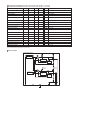

Block Diagram
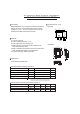
Electrical characteristics (Unless otherwise noted; Ta=25˚C, Vcc=5V)
∗2
∗2
Parameter Symbol Min. Typ. Max. Unit Conditions
Io=0mA, Io2=0mA
Io1=500mA
Io1=500mA, Vcc=3.135V
f=120Hz, ein=1Vrms, Io1=200mA
Vcc=4.1 → 16V, Io1=500mA
Io1=0mA → 1A
Io1=5mA, Tj=0~125˚C
Vcc=16V
Io2=500mA
f=120Hz, ein=1Vrms, Io2=200mA
Vcc=4.1 → 16V, Io2=500mA
Io2=0mA → 1A
Io1=5mA, Tj=0~125˚C
Vcc=16V
Ib
Vo1
∆Vd1
Io1
R.R. 1
Reg.I1
Reg.L1
Tcvo1
IOS1
Vo2
Io2
R.R. 2
Reg.I2
Reg.L2
Tcvo2
IOS2
-
3.234
-
1.0
50
-
-
-
-
2.450
1.0
50
-
-
-
-
0.8
3.3
0.25
-
58
5
30
±0.01
300
2.5
-
58
5
30
±0.01
270
1.5
3.366
0.50
-
-
30
75
-
-
2.550
-
-
30
75
-
-
mA
V
V
A
dB
mV
mV
% /
˚C
mA
V
A
dB
mV
mV
% /
˚C
mA
Bias current
<3.3V output>
Output voltage 1
Min. I/O voltage difference 1
Output current capacity 1
Ripple rejection 1
Input stability 1
Load stability 1
Output voltage temperature
coefficient 1
Output short current 1
<2.5V output>
Output voltage 2
Output current capacity 2
Ripple rejection 2
Input stability 2
Load stability 2
Output voltage temperature
coefficient 2
Output short current 2
∗This product is not designed for protection against radioactive rays.
∗2 Design guaranteed (All total inspection is not performed.)
Reference
Voltage
Sat.
Prevention
Current
Limit
Current
Limit
Sat.
Prevention
Thermal
Shut Down
Vcc Vcc
Vcc Vcc
Vcc Vo2GND(FIN) Vo1N.C.
BA33C25FP/HFP