
User guide

Operating voltage range
Circuit current 1
Circuit current 2
Standby circuit current
Input voltage "H" level
Input voltage "L" level
"H" level input current
Output saturation voltage
Power save OFF voltage
Power save ON voltage
REF bias current
Icc1
Icc2
IST
VIH
VIL
IIH
VCE
VPS OFF
VPS ON
IREF
mA
mA
A
V
V
V
V
V
A
V
CC
V
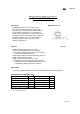
6.5 - 34
12
8
15
-
0.8
300
3.3
0.8
-
35
8
5
-
-
-
200
2.2
-
-
12
5
3
3.0
-
100
-
-
2.0
-
Forward or reverse mode
Brake mode
Standby mode
VIN=3.0V
Io=200mA
(Sum of C-E voltage on upper and lower output Tr)
Operate mode
Standby mode
VREF=6V, Io=100mA
(Unless otherwise noted, Ta=25 , Vcc=12V, VM=12V)
Recommended Operating Conditions (Ta=25 )
Electrical characteristics
ConditionsParameter Symbol UnitMin. Typ. Max.
Parameter Symbol UnitMin. Typ. Max.
V
M
V6.5 - 34
-
*This product is not designed for protection against radioactive rays.
A
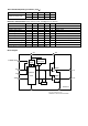
Block diagram
Rin
Fin
VREF
REFERENCE
VOLTAGE
GND
RNF
VM
DRIVER
OUT1
BA6920FP-Y
1617
8
6
Vcc
9
5
OUT2
20
21
18
DRIVER
POWER
SAVE
TSD
1~4.7.10~15.22~25 : N.C.
*Radiation fin must connect with GND.
CONTROL
LOGIC
POWER SAVE
19