
User guide

BG12864C1
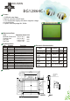
Feature
Mechanical Data
Item
Module Dimension
Viewing Area
Dot Size
Dot Pitch
Standard Value Unit
Pin Assignment
Pin Symbol Function
1
2
3
4
5
6
7
Chip select for IC1
Chip select for IC2
GND
Power supply (+5V)
Contrast adjustment
Data / instruction
/CS1
/CS2
Vss
Vdd
Vo
D/I
R/W
mm
mm
mm
mm
78.0 x 70.0
62.0 x 44.0
0.42 x 0.58
0.44 x 0.60
Dimension
BO LYMIN
1. COB with metal frame
2. Built-in controller KS0107/0108
3. +5V single power supply, with built-in negative voltage
4. 1/64 duty cvcle
5. Option: LED array/edge B/L, EL B/L
8
9~16
Data bus line
E
DB0~7
17
18
Reset signal
Negative voltage output
/RST
Vee
Input Voltage
Supply Current
LCD Driving
Voltage
LED Forward
Voltage
LED Forward
Current
Vdd
Idd
Vdd-Vo
Vf
If
Vdd = +5V
Vdd = +5V
25 C
5.0
9.7
9.1
4.2
480
V
mA
V
V
mA
Typical
Value
Electronic Characteristics
o
25 C
o
25 C
o
Item Symbol Condition
Unit
EL Power
Voltage
Vel
Vel=110Vac/400Hz
V
Data read/write
H -->L Enable signal
19
20
Power supply for B/L (+)
P
o
w
e
r
s
u
p
p
l
y
f
o
f
r
B/L (G
N
D
)
A
K
0
.
4
2
0
.
4
4
0
.
5
8
0
.
6
1
2
8
X
6
4
4
D
o
t
s
5
6
.
3
(
A
A
A
)
6
2
.
0
(
V
A
)
P
2
.
5
4
*
1
5
=
3
8
.
1
7
4
.
0
1
5
.
3
8
.
3
8
(
A
A
A
)
1
4
4
.
0
(
V
A
)
7
.
4
5
5
.
2
7
0
.
0
0
.
5
7
8
.
0
0
.
5
6
8
.
0
5
.
0
2
8
.
0
2
.
5
4
6
4
.
9
2
A
K
2
.
5
4
a
r
r
a
y
l
e
d
9
.
7
e
d
g
e
l
e
d
7
.
5
e
l
/
r
e
f
5
.
1
a
r
r
a
y
l
e
d
1
4
.
3
e
d
g
e
l
e
d
1
2
.
1
e
l
/
r
e
f
9
.
7
1
.
6
2
.
2
5
4
-
Ø
2
.
5
P
T
H
4
-
Ø
5
.
0
P
A
D
Ø
1
.
0
±
±