
User guide
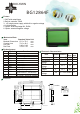

BG12864F
Feature
Mechanical Data
Item
Module Dimension
Viewing Area
Dot Size
Dot Pitch
Standard Value Unit
Pin Assignment
Pin Symbol Function
1
2
3
4
5
6
7~14
GND
Power supply(+5V)
Contrast adjustment
Command/data read/write
Data read
Data write
Vss
Vdd
Vo
C/D
/RD
/WR
DB0~7
mm
mm
mm
mm
87.0 x 70.0
72.0 x 40.0
0.48 x 0.48
0.52 x 0.52
Dimension
BO LYMIN
1. SMT with metal frame
2. Built-in controller T6963
3. +5V single power supply, with built-in negative voltage
4. 1/64 duty cycle
5. Option: LED array/edge B/L, EL B/L
6. Option: external negative voltage
15
16
Reset signal
/CE
/RST
17
18
Negative voltage output -5V
Column No. selection
(H:32 column, L: 40 columns)
Vee
MD2
Data bus line
Chip enable
19
20
Font selection (H:6x8,L:8x8)
H: normal L: stop clock oscillation
FS
HLT
Input Voltage
Supply Current
LCD Driving
Voltage
LED Forward
Voltage
LED Forward
Current
Vdd
Idd
Vdd-Vo
Vf
If
Vdd = +5V
Vdd = +5V
25 C
5.0
9.7
8.5
4.2
330
V
mA
V
V
mA
Typical
Value
Electronic Characteristics
o
25 C
o
25 C
o
Item Symbol Condition
Unit
EL Power
Voltage
Vel
Vel=110Vac/400Hz
V
7
0
.
0
±
0
.
5
5
0
.
2
4
0
.
0
(
V
A
)
3
3
.
2
4
(
A
A
A
A
)
8
2
.
0
2
0
-
Ø
1
.
0
P
T
H
2
0
-
Ø
1
.
8
P
A
D
1
.
6
7
2
.
0
(
V
A
)
8
7
.
0
±
0
.
5
7
7
.
2
6
6
.
5
2
(
A
A
A
)
7
1
0
2
2
.
8
6
2
.
5
6
5
.
0
4
-
Ø
3
.
2
P
T
H
4
-
Ø
5
.
0
P
A
D
0
.
4
8
0
.
5
2
0
.
4
8
0
.
5
2
(
P
2
.
5
4
*
9
)
2
.
5
4
1
.
5
1
5
.
4
S
C
A
L
E
1
0
/
1
1
3
.
1
(
L
E
D
B
/
L
)
9
.
2
(
E
L
o
r
N
o
B
/
L
)
9
.
0
(
L
E
D
B
/
L
)
(
E
L
o
r
N
o
B
/
L
)