
Manual

1
Standard ICs
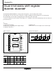
Dual 4-bit static shift register
BU4015B / BU4015BF
The BU4015B and BU4015BF are 4-stage static shift registers, each consisting of two circuits.
The D flip-flops for each stage share a common reset input, enabling external asynchronous reset at any point.
Also, the flip-flops at each stage are triggered by the rising edge of the clock input.
“H” level reset input resets the contents of all stages to “L”, regardless of the clock and data input, and sets data out-
puts Q0 to Q3 to “L”.
•
Features
1) Low power dissipation.
2) Wide range of operating power supply voltages.
3) High input impedance.
4) High fan-out.
5) Direct drive of 2 L-TTL inputs and 1 LS-TTL input.
•
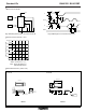
Block diagram
2
Q
3B
Q1A
Q0A
DA
Q2B
3
4
5
6
RESET
A
7
8
15
14
13
12
11
10
9
V
SS
1
CLOCK
B
D
B
VDD
Q0B
Q1B
Q2B
Q3A
RESET
B
CLOCK
A
16
Q3 Q2 Q1
CL R D
Q
0
CL R D
Q
0 Q1 Q2
Q3
•
Logic circuit diagram
D
Q
0 Q1 Q2 Q3
CLOCK
RESET
DQ
CL
Q
R
DQ
CL
Q
R
DQ
CL
Q
R
DQ
CL
Q
R
•
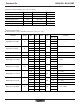
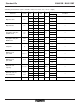
Truth table
CLOCK D RESET Q
0
Q
1
Q
2
Q
3
LL LQ
0
Q
1
Q
2
HL HQ
0
Q
1
Q
2
X L No Change
XXH L L L
L
X : Irrelevant