
Manual


Copyright 1997 by Dallas Semiconductor Corporation.
All Rights Reserved. For important information regarding
patents and other intellectual property rights, please refer to
Dallas Semiconductor data books.
DS1215
Phantom Time Chip
DS1215
032697 1/15
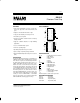
FEATURES
• Keeps track of hundredths of seconds, seconds, min-
utes, hours, days, date of the month, months, and
years
• Adjusts for months with fewer than 31 days
• Leap year automatically corrected up to 2100
• No address space required
• Provides nonvolatile controller functions for battery
backup of RAM
• Supports redundant batteries for high–reliability
applications
• Uses a 32.768 KHz watch crystal
• Full ±10% operating range
• Operating temperature range 0°C to 70°C
• Space-saving, 16–pin DIP package and SOIC
• Optional industrial temperature range –40°C to +85°C
(IND)
DESCRIPTION
The DS1215 Phantom Time Chip is a combination of a
CMOS timekeeper and a nonvolatile memory controller.
In the absence of power, an external battery maintains
the timekeeping operation and provides power for a
CMOS static RAM. The watch keeps track of hun-
dredths of seconds, seconds, minutes, hours, day, date,
month, and year information. The last day of the month
is automatically adjusted for months with less than 31
days, including correction for leap year every four years.
The watch operates in one of two formats: a 12–hour
mode with an AM/PM indicator or a 24–hour mode. The
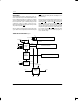
nonvolatile controller supplies all the necessary support
circuitry to convert a CMOS RAM to a nonvolatile
memory. The DS1215 can be interfaced with either
RAM or ROM without leaving gaps in memory.
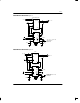
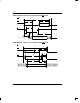
PIN ASSIGNMENT
1
2
3
4
5
6
7
8
16
15
14
13
12
11
10
9
X1
X2
WE
BAT1
GND
D
Q
GND
V
CCI
V
CCO
BAT2
RST
OE
CEI
CEO
ROM/RAM
16–PIN DIP (300 MIL)
1
2
3
4
5
6
7
8
16
15
14
13
12
11
10
9
X1
X2
WE
BAT1
GND
D
Q
GND
V
CCI
V
CCO
BAT2
RST
OE
CEI
CEO
ROM/RAM
16–PIN SOIC (300 MIL)
PIN DESCRIPTION
X1, X2 – 32.768 KHz Crystal Connections
WE – Write Enable
BAT1 – Battery 1 Input
GND – Ground
D – Data In
Q – Data Out
ROM/RAM
– ROM/RAM Select
CEO
– Chip Enable Out
CEI – Chip Enable Input
OE – Output Enable
RST – Reset
BAT2 – Battery 2 Input
V
CCO
– Switched Supply Output
V
CCI
– +5 VDC Input
NOTE: Both pins 5 and 8 must be grounded.
ORDERING INFORMATION
DS1215 16–pin DIP
DS1215S 16–pin SOIC
DS1215N 16–pin DIP (IND)
DS1215SN 16–pin SOIC (IND)