
User guide


DS1254
14 of 17
NOTES:
1) Voltage referenced to ground.
2) These parameters are sampled with a 50pF load and are not 100% tested.
3) BW is an open-drain output and, as such, cannot source current. An external pullup resistor should be
connected to this pin for proper operation. BW can sink 10mA.
4) The DS3800 battery cap is a one-time use part, but can be removed and replaced. By Design, DS3800
removal will mechanically damage the battery cap, which eliminates the accidental use of a
previously attached and possibly low capacity battery cap.
5) t
WP
specified as the logical AND of CE and WE , t
WP
is measured from the latter of CE or WE going
low to the earlier of CE or WE going high.
6) T
AH1
, t
DH1
are measured from WE going high.
7) T
AH2
, t
DH2
are measured from CE going high.
8) t
DS
is measured from the earlier of CE or WE going high.
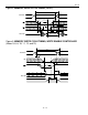
9) WE is high for a read cycle.
10) OE = V
IH
or V
IL
. If OE = V
IH
during write cycle, the output buffers remain in a high-impedance state.
11) If the CE low transition occurs simultaneously with or later than the WE low transition in a write-
enable-controlled write cycle, the output buffers remain in a high-impedance state during this period.
12) If the CE high transition occurs prior to or simultaneously with the WE high transition, the output
buffers remain in a high-impedance state during this period.
13) If WE is low or the WE low transition occurs prior to or simultaneously with the CE low transition,
the output buffers remain in a high impedance state during this period.
14) In a power-down condition, the voltage on any pin cannot exceed the voltage on V
CC
.