
User guide

Copyright 1995 by Dallas Semiconductor Corporation.
All Rights Reserved. For important information regarding
patents and other intellectual property rights, please refer to
Dallas Semiconductor databooks.
DS1667
Digital Resistor with OP AMP
DS1667
021492 1/11
FEATURES
• Two digitally controlled 256-position potentiometers
• Serial port provides means for setting and reading
both potentiometers
• Resistors can be connected in series to provide addi-
tional resolution
• Default wiper position on power up is 50%
• Resistive elements are temperature compensated to
+
20% end to end
• Two high gain wide bandwidth operational amplifiers
• Low power CMOS design
• Applications include analog–to–digital and digital–to–
analog converters, variable oscillators, and variable
gain amplifiers
• 20–pin DIP package or optional 20–pin SOIC surface
mount package
• Operating temperature range of 0°C to 70°C
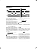
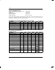
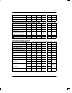
• Resistance Values
RESOLUTION -3 dB POINT
DS1667-10: 10K 39 ohms 1.1 MHz
DS1667-50: 50K 195 ohms 200 kHz
DS1667-100: 100K 390 ohms 100 kHz
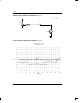
PIN ASSIGNMENT
V
CC
OUT0
SOUT
W0
H0
L0
COUT
DQ
INVI
NINVI
NINV0
INV0
V
B
W1
H1
L1
RST
CLK
OUT1
GND
1
2
3
4
5
6
7
8
9
10
20
19
18
17
16
15
14
13
12
11
20-Pin DIP (300 Mil) and 20-Pin SOIC
PIN DESCRIPTION
V
CC
- +5 Volt Supply
GND - Ground
L0, L1 - Low End of Resistor
H0, H1 - High End of Resistor
W0, W1 - Wiper End of Resistor
V
B
- Substrate Bias and OP AMP
Negative Supply
SOUT - Wiper for Stacked
Configuration
RST
- Serial Port Reset Input
DQ - Serial Port Input/Output
CLK - Serial Port Clock Input
COUT - Cascade Serial Port Output
NINV0, NINVI - Noninverting OP AMP Input
INV0, INVI - Inverting OP AMP Input
OUT0, OUT1 - OP AMP Outputs
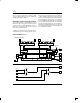
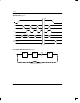
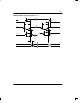
DESCRIPTION
The DS1667 is a dual–solid state potentiometer that is
adjustable by digitally selected resistive elements.
Each potentiometer is composed of 256 resistive ele-
ments. Between each resistive section of each poten-
tiometer are tap points accessible to the wiper. The po-
sition of the wiper on the resistive array is set by an 8–bit
register that controls which tap point is connected to the
wiper output. Each 8–bit register can be read or written
by sending or receiving data bits over a 3–wire serial
port. In addition, the resistors can be stacked such that
a single potentiometer of 512 sections results. When
two separate potentiometers are used, the resolution of
the DS1667 is equal to the resistance value divided by
256. When the potentiometers are stacked end to end,
the resistance value is doubled while the resolution re-
mains the same. The DS1667 also contains two high
gain wide bandwidth operational amplifiers. Each am-
plifier has both the inverting and non-inverting inputs
and the output available for user configuration. The op-
erational amplifiers can be paired with the resistive ele-