
Owner manual


DS1720
030598 11/12
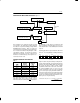
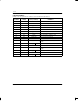
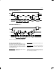
AC ELECTRICAL CHARACTERISTICS (–55°C to +125°C; V
DD
=2.7V to 5.5V)
PARAMETER SYMBOL MIN TYP MAX UNITS NOTES
Temperature Conversion Time T
TC
400 1000 ms
Data to CLK Setup t
DC
35 ns 6
CLK to Data Hold t
CDH
40 ns 6
CLK to Data Delay t
CDD
100 ns 6, 7, 8
CLK Low Time t
CL
285 ns 6
CLK High Time t
CH
285 ns 6
CLK Frequency f
CLK
DC 1.75 MHz 6
CLK Rise and Fall t
R
, t
F
500 ns
RST to CLK Setup t
CC
100 ns 6
CLK to RST Hold t
CCH
40 ns 6
RST Inactive Time t
CWH
125 ns 6, 9
CLK High to I/O High–Z t
CDZ
50 ns 6
RST Low to I/O High–Z t
RDZ
50 ns 6
Convert Pulse Width t
CNV
250 ns 500 ms
NV Write Cycle Time t
WR
10 50 ms 12
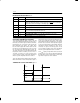
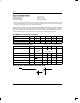
AC ELECTRICAL CHARACTERISTICS (–55°C to +125°C; V
DD
=2.7V to 5.5V)
PARAMETER SYMBOL MIN TYP MAX UNITS NOTES
Input Capacitance C
I
5 pF
I/O Capacitance C
I/O
10 pF
NOTES:
1. All voltages are referenced to ground.
2. Logic one voltages are specified at a source current of 1 mA.
3. Logic zero voltages are specified at a sink current of 4 mA.
4. I
CC
specified with DQ pin open and CLK pin at V
DD
.
5. I
CC
specified with V
CC
at 3.3V and RST=GND.
6. Measured at V
IH
= 2.0V or V
IL
= 0.6V.
7. Measured at V
OH
= 2.4V or V
OL
= 0.4V.
8. Load capacitance = 50 pF.
9. t
CWH
must be 10 ms minimum following any write command that involves the E
2
memory.
10.See typical curve for specification limits outside 0°C to 85°C range.
11. Thermometer error reflects temperature accuracy as tested during calibration.
12.Writing to the nonvolatile memory should only take place in the 0°C to 70°C temperature range.